Valve of fluid bag
A fluid bladder and valve technology, applied in diaphragm valves, valve devices, engine components, etc., can solve the problems of complex valve structure, large volume and weight, and high price, and achieve simple and safe operation, small volume and height, and low production costs. Effect
- Summary
- Abstract
- Description
- Claims
- Application Information
AI Technical Summary
Problems solved by technology
Method used
Image
Examples
Embodiment 1
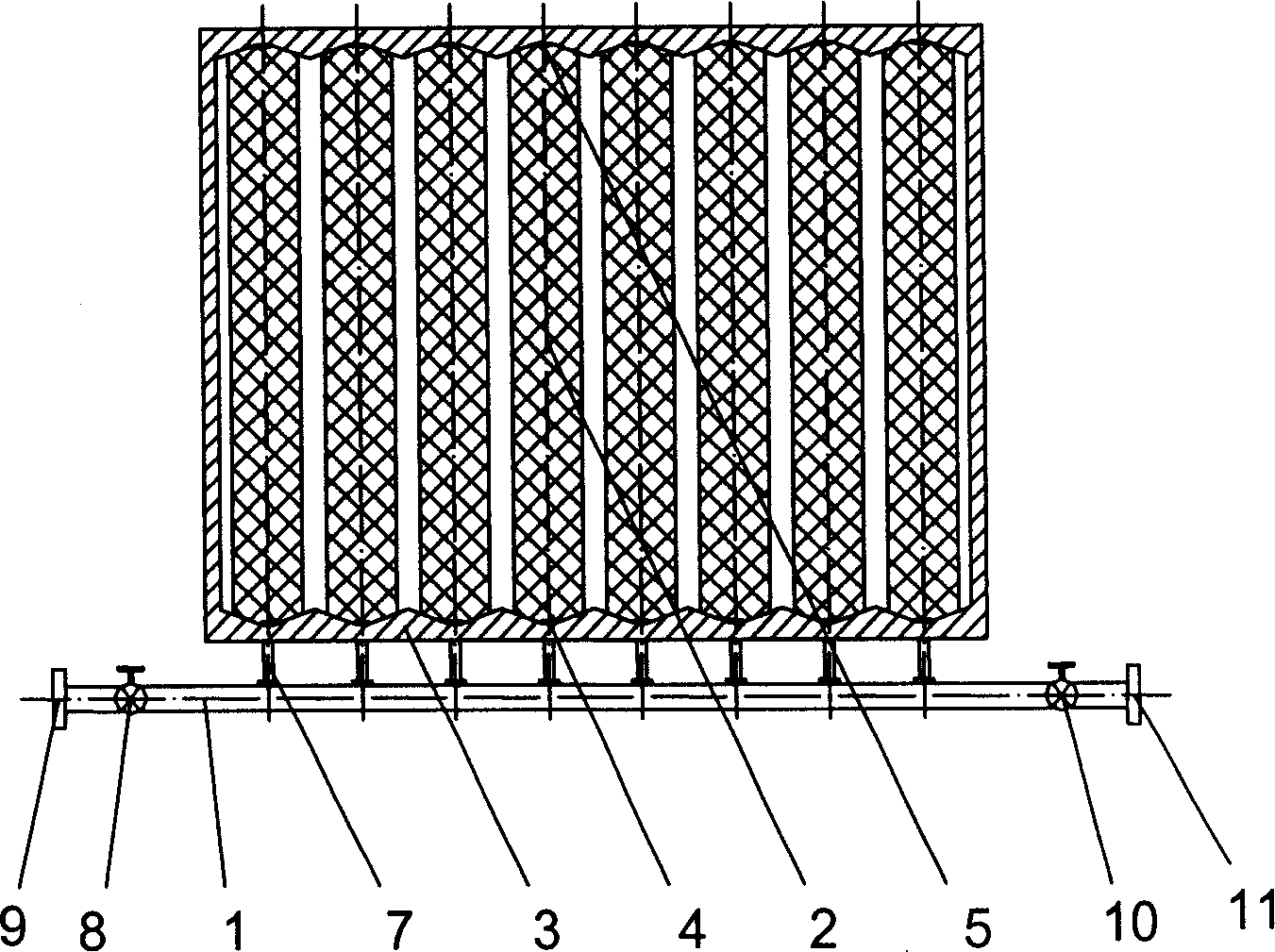
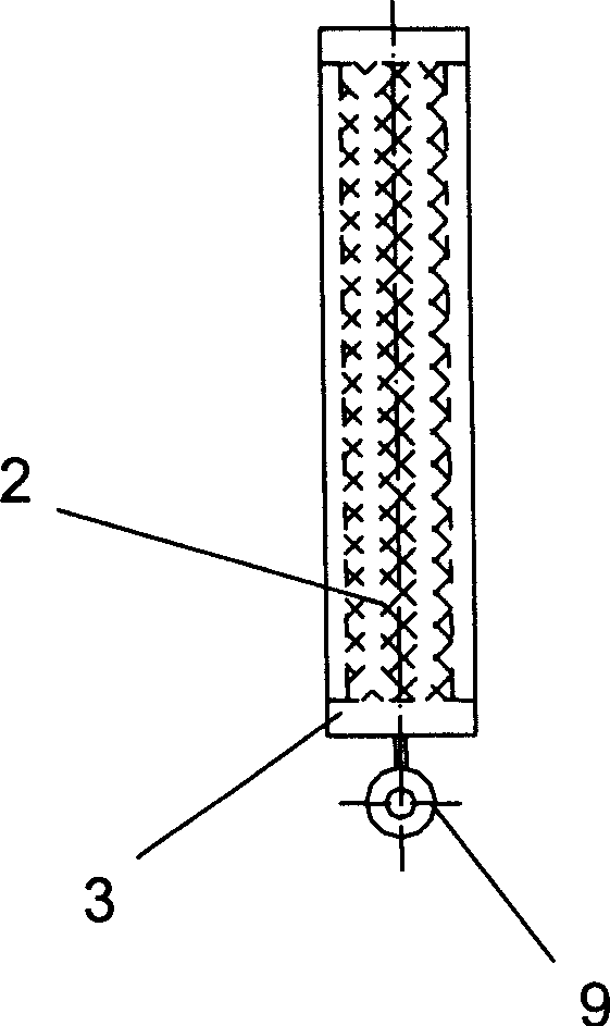
[0035] As shown in FIG. 2 , the valve includes a main fluid pipe 1 , several fluid capsules 2 , and a valve housing 3 . One end 4 and the other end 5 of the fluid capsule 2 are fixed and sealed with the valve housing 3 . The main fluid pipe 1 communicates with each fluid bag 2 through a plurality of branch fluid pipes 7. There is an inlet fluid control valve 8 and a flange 9 at one end of the main fluid pipe 1, and an outlet fluid control valve 10 and a flange at the other end. 11. The flange 9 is connected to a pressure fluid source (such as an air compressor, a hydraulic pump, a water pipe network, etc.), and the flange 11 is connected to a negative pressure device. The opening and closing of the inlet fluid control valve 8 and the outlet fluid control valve 10 can be controlled manually or automatically.
[0036] image 3 Because the valve is in a closed state, when the valve needs to be closed, first make the outlet fluid control valve 10 in a closed state, open the inle...
Embodiment 2
[0039] Such as Figure 5 As shown, in this embodiment, its structure is basically the same as that of the embodiment. In order to enhance the stability of the position of the fluid capsule 2 in the valve, a rigid support rod 12 can be added inside each fluid capsule 2, which can basically limit The swing range of the fluid bladder.
Embodiment 3
[0041] Such as Image 6 As shown, in the structure of this embodiment, a branch control valve 13 can be installed in each branch pipe 7 to control the entry and exit of the pressure fluid of each fluid bag 2, so that the valve has a more stable flow regulation function, that is, By controlling the opening of each branch control valve 13, some fluid capsules 2 are filled with pressurized fluid, while some fluid capsules 2 are not filled with pressurized fluid, so that different valve opening areas can be obtained, and the flow regulating function of the valve can be realized. In addition, a partition 14 can also be set between each fluid capsule 2, and the two ends of the partition 14 are fixed to the valve housing 3. When each fluid capsule 2 is in close contact, there is a partition 14 in the middle, so that each When the fluid capsule 2 expands independently, the fluid capsule 2 will be in close contact with each partition 14, which is more conducive to the realization of th...
PUM
 Abstract
Description
Claims
Application Information
 - R&D
- Intellectual Property
- Life Sciences
- Materials
- Tech Scout
- Unparalleled Data Quality
- Higher Quality Content
- 60% Fewer Hallucinations
Browse by: Latest US Patents, China's latest patents, Technical Efficacy Thesaurus, Application Domain, Technology Topic, Popular Technical Reports.
© 2025 PatSnap. All rights reserved.Legal|Privacy policy|Modern Slavery Act Transparency Statement|Sitemap|About US| Contact US: help@patsnap.com


