Cavity filter with rotary coupling regulation structure

A cavity filter and coupling adjustment technology, which is applied in the microwave cavity filter and radio frequency fields, can solve the problems such as capacitive coupling is not easy to adjust, and achieve the effect of novel structure, small size, and easy production and assembly

Inactive Publication Date: 2011-07-13
东台君安电子科技有限公司
View PDF6 Cites 27 Cited by
  • Summary
  • Abstract
  • Description
  • Claims
  • Application Information

AI Technical Summary

Problems solved by technology

[0004] The technical problem to be solved by the present invention is to provide a cavity filter with a rotary coupling adjustment structure, which solves the problem

Method used


Image

  • Cavity filter with rotary coupling regulation structure
  • Cavity filter with rotary coupling regulation structure
  • Cavity filter with rotary coupling regulation structure

Examples


Embodiment 1

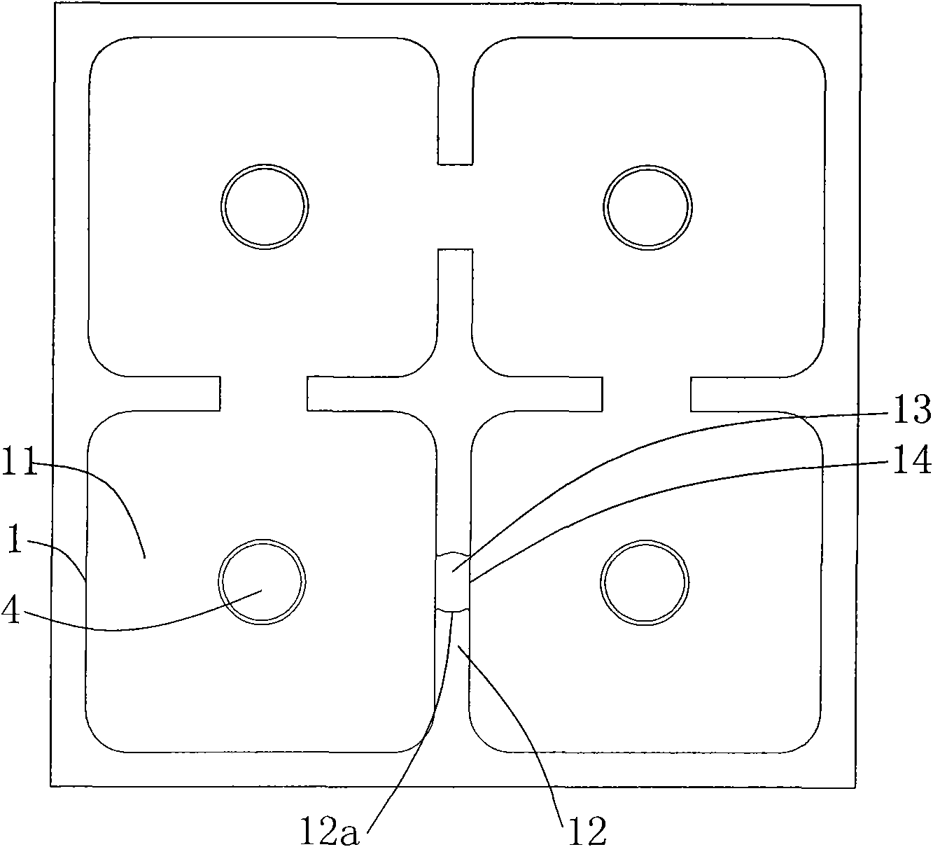
[0030] The cavity filter with a rotary coupling adjustment structure in this embodiment includes a body 1 and a cover plate 2, the body 1 is formed with four resonant cavities 11, and the capacitive couplers are arranged on the two resonant cavities on both sides of the passband of the filter Between 11.

[0031] Such as figure 1 As shown, a partition wall 12 is provided between the resonant cavities 11, and the partition wall 12 is formed with a cylindrical groove 13 with an arc-shaped inner wall surface 12a. Both sides of the cylindrical groove 13 are formed with openings 14 corresponding to the resonant cavity 11.

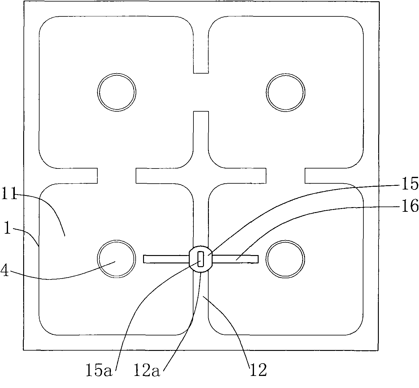
[0032] Such as figure 2 As shown, a cylindrical insulating support block 15 is rotated in the cylindrical groove 13, and a capacitive coupler is installed in the insulating support block 15. The outer end of the capacitive coupler passes through the opening 14, and the resonant cavity 11-phase coupled.

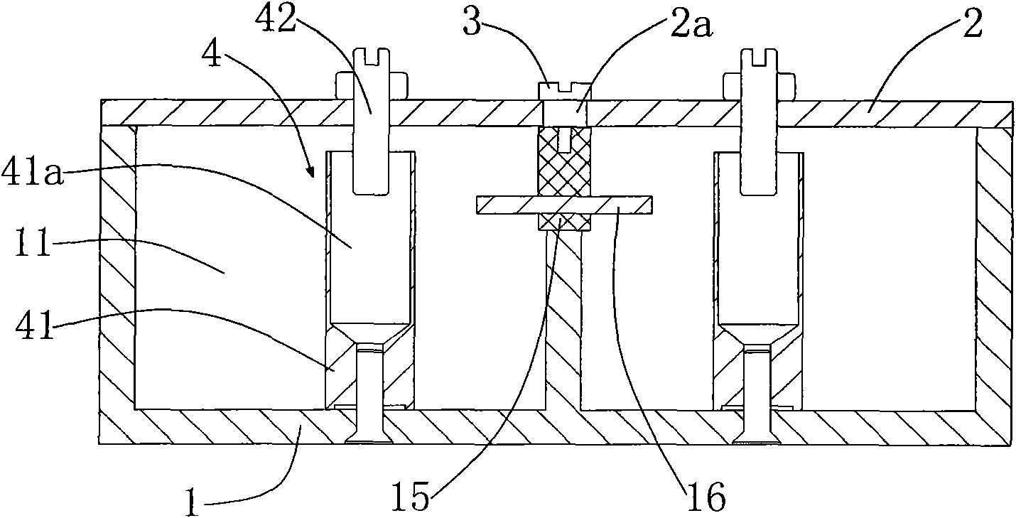
[0033] A resonator 4 is fixed inside the resonant cavi...

Embodiment 2

[0039] The cavity filter with a rotary coupling adjustment structure in this embodiment includes a body 1 and a cover plate 2. The body 1 is formed with three resonant cavities 11 arranged in a triangle, and the capacitive coupler is arranged at the low end of the passband of the filter. Between the two resonators 11.

[0040] Such as Figure 4 As shown, a partition wall 12 is provided between the resonant cavities 11, and the partition wall 12 is formed with a cylindrical groove 13 with an arc-shaped inner wall surface 12a. Both sides of the cylindrical groove 13 are formed with openings 14 corresponding to the resonant cavity 11.

[0041] Such as Figure 5 As shown, a cylindrical insulating support block 15 is rotated in the cylindrical groove 13, and a capacitive coupler is installed in the insulating support block 15. The outer end of the capacitive coupler passes through the opening 14, and the resonant cavity 11-phase coupled.

[0042] A resonator 4 is fixed inside th...

Embodiment 3

[0048] On the basis of Embodiment 1 or Embodiment 2, the capacitive coupler of this embodiment is as Figure 8 As shown, expansion parts 16b are formed at both ends of the metal body 16, and the capacitive coupler is dumbbell-shaped as a whole.


PUM

PropertyMeasurementUnit
Depthaaaaaaaaaa

Abstract

The invention discloses a cavity filter with a rotary coupling regulation structure, comprising a body and a cover plate, wherein at least three resonant cavities are arranged at the body, bulkheads are arranged among the resonant cavities; a cylindrical groove with an arc-shaped inner wall surface is arranged in each bulkhead; openings corresponding to the resonant cavities are arranged at the two sides of the cylindrical groove; the rotary coupling regulation structure is rotationally matched in the cylindrical groove; the rotary coupling regulation structure comprises a cylindrical insulation supporting block and a capacitive coupler fixedly arranged on the insulation supporting block; the insulation supporting block is provided with arc-shaped outer wall surface matched with the cylindrical groove; and the outer end of the capacitive coupler penetrates the openings and is coupled with the resonant cavities. Through the rotary coupling regulation structure, the capacitive cross coupling strength of the cavity filter can be very conveniently regulated from the outside of the cover plate.

Description

technical field [0001] The invention relates to a radio frequency and microwave cavity filter, in particular to a cavity filter with a rotary coupling adjustment structure. Background technique [0002] With the continuous development of wireless communication technology, the transmission power is getting higher and higher, and the frequency resources are getting tighter and tighter. In order not to interfere with each other, the transmission and reception signals of the same communication system need high transceiver suppression; different communication systems and communication modes need good anti-interference ability, and it is also required that the out-of-band signal be as large as possible. fade away. The division, development and utilization of all frequency bands are realized with filters. The microwave radio frequency device that can withstand high power, small loss, and high suppression is undoubtedly a coaxial cavity filter. The design principle of the cavity ...

Claims


Application Information

Patent Timeline
IPC IPC(8): H01P1/208
Inventor 倪达王战军张中玉
Owner 东台君安电子科技有限公司
Why Eureka
Try Eureka