Spark plug and method of manufacturing the same

A technology of spark plugs and precious metals, which is applied in the field of spark plugs and its manufacturing, can solve the problems of increased cost and expensive precious metal alloys, and achieve the effect of suppressing discharge and improving durability

Active Publication Date: 2011-07-13
NGK SPARK PLUG CO LTD
View PDF8 Cites 4 Cited by
  • Summary
  • Abstract
  • Description
  • Claims
  • Application Information

AI Technical Summary

Problems solved by technology

However, since the noble metal alloy constituting the noble metal tip is relatively expensive, if the alread...

Method used


Image

  • Spark plug and method of manufacturing the same
  • Spark plug and method of manufacturing the same
  • Spark plug and method of manufacturing the same

Examples


no. 1 approach

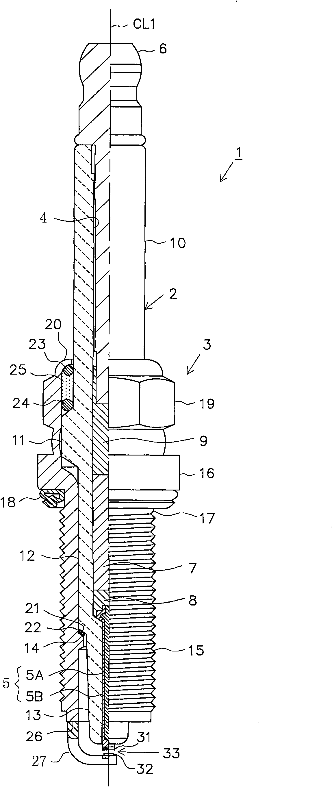
[0060] Next, embodiments will be described with reference to the drawings. figure 1 It is a partially cutaway front view showing the spark plug 1 . In addition, in figure 1 Here, the axis CL1 direction of the spark plug 1 is regarded as the vertical direction in the drawing, the lower side in the drawing is regarded as the front end side of the spark plug 1 , and the upper side in the drawing is regarded as the rear end side of the spark plug 1 .

[0061] The spark plug 1 includes members such as a cylindrical porcelain insulator 2 serving as an insulator, and a cylindrical main body metal shell 3 holding the insulator 2 .

[0062] The ceramic insulator 2 is formed by sintering alumina or the like as known, and the outer shape of the porcelain insulator 2 includes: a rear end side body portion 10 formed on the rear end side; a large diameter portion 11 protruding radially outward. Formed on the front end side of the rear end side body part 10; the middle body part 12, which ...

no. 2 approach

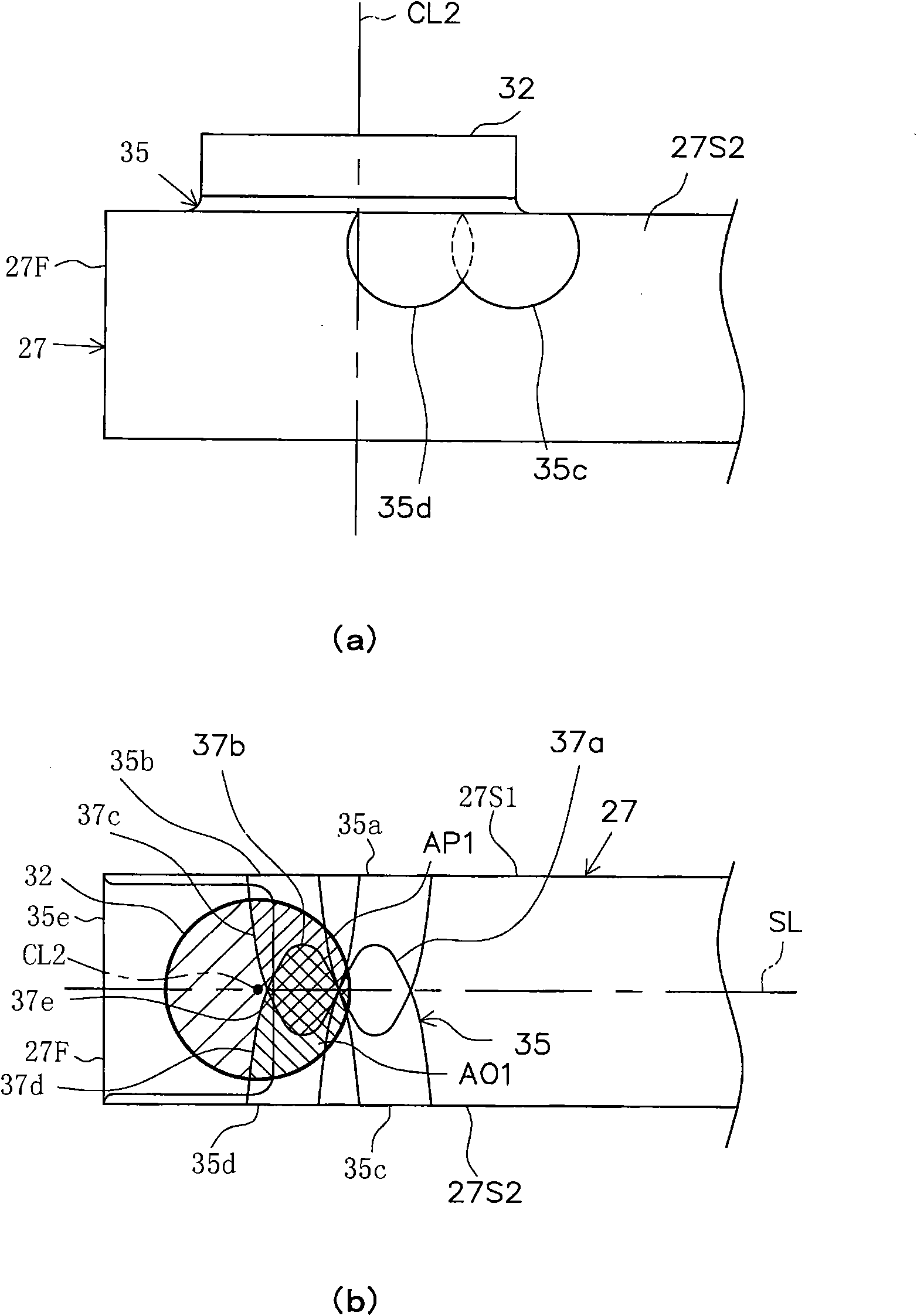
[0099] Next, a second embodiment will be described focusing on differences from the first embodiment described above with reference to the drawings. In this second embodiment, if Figure 8 As shown in (a) and (b), in particular, when the noble metal tip 32 is bonded to the ground electrode 27, the irradiation position of the laser beam or the electron beam is different, resulting in a different structure of the fusion zone 45 formed.

[0100] Specifically, the melting portion 45 is composed of melting regions 45a, 45b, 45c, 45d, 45e, 45f, 45g, and 45h. Laser beams or electron beams are irradiated to four positions on the side surface 27S1 of the ground electrode 27 in a direction parallel to the discharge surface and in a direction perpendicular to the longitudinal direction of the ground electrode 27, thereby forming molten regions 45a, 45b, 45c, and 45d. In addition, the fusion regions 45e, 45f, 45g, and 45h are formed by irradiating laser beams or electron beams in a direc...


PUM


Abstract

The present invention provides a spark plug in which a noble metal tip having a relatively large diameter is joined to a ground electrode, and which can restrain an increase in cost while sufficiently ensuring separation resistance of the noble metal tip, as well as a method of manufacturing the same. A spark plug including a noble metal tip joined to a ground electrode and forming a spark discharge gap in cooperation with a center electrode. A surface of the noble metal tip which forms the gap has an area of 0.9 mm2 or greater. The noble metal tip (32) is joined to the ground electrode (27) via a fusion zone (35) formed by irradiating at least one surface among a distal end surface and side surfaces of the ground electrode with a laser beam or an electron beam. Further, as viewed on a projection plane orthogonal to a center axis of the noble metal tip and on which the noble metal tip and the fusion zone are projected along the center axis, an overlapping region between the noble metal tip (32) and the fusion zone accounts for 70% or more of a projected region of the noble metal tip.

Description

technical field [0001] The present invention relates to a spark plug used in an internal combustion engine and the like and a method of manufacturing the same. Background technique [0002] A spark plug for a combustion device such as an internal combustion engine includes, for example, a center electrode extending in the axial direction, an insulator provided on the outer periphery of the center electrode, a cylindrical main body metal shell assembled outside the insulator, and a base end portion and the main body metal shell. The tip portion of the bonded ground electrode. The ground electrode is arranged by bending the substantially middle portion of itself so that the front end of the ground electrode faces the front end of the center electrode, thereby forming a spark between the front end of the center electrode and the front end of the ground electrode. discharge gap. [0003] In addition, in recent years, a technique has been known in which a noble metal tip is joi...

Claims


Application Information

Patent Timeline
IPC IPC(8): H01T13/22H01T13/34H01T21/02
CPCH01T13/32H01T21/02
Inventor 坂柳伸彰中山胜稔
Owner NGK SPARK PLUG CO LTD
Why Eureka
Try Eureka