Current diagnosing device and method for monitoring state of current transformer

A technology for current transformers and diagnostic devices, applied in the field of current diagnostic devices, can solve problems such as reducing current sampling accuracy, increasing signal processing steps, and current distortion, so as to avoid adverse effects, improve sampling accuracy, and save hardware resources.

Active Publication Date: 2011-07-13
SHANGHAI NOARK ELECTRIC
View PDF5 Cites 56 Cited by
  • Summary
  • Abstract
  • Description
  • Claims
  • Application Information

AI Technical Summary

Problems solved by technology

The defect of the above existing technologies is that an external signal must be introduced into the current transformer, which will directly affect the sampling signal of the current transformer and cause distortion of the current sampling, so calibration measures must be taken at the back end for correction, such as US2007006

Method used


Image

  • Current diagnosing device and method for monitoring state of current transformer
  • Current diagnosing device and method for monitoring state of current transformer
  • Current diagnosing device and method for monitoring state of current transformer

Examples


Embodiment Construction

[0033] Attached below Figures 1 to 4 The illustrated embodiment is only used as a non-limiting example to further describe in detail the current diagnostic device for monitoring the state of a current transformer and the diagnostic method thereof of the present invention. and from the following combination Figure 5-10 Other advantages and features of the present invention can be seen more clearly in the description of the simulation test results performed.

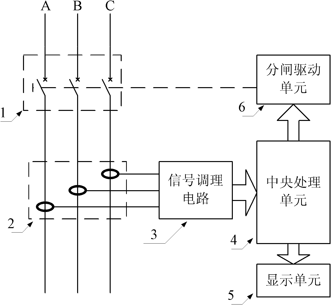
[0034] figure 1 It is a circuit block diagram of the current diagnosis device for monitoring the state of the current transformer of the present invention. Such as figure 1 As shown, the current diagnosis device of the present invention includes a current transformer 2 connected to the load side of the circuit breaker 1, a signal conditioning circuit 3 connected between the secondary coil output terminal of the current transformer 2 and the input terminal of the central processing unit 4 , a display unit 5 and a gate...


PUM


Abstract

A current diagnosing device for monitoring the state of a current transformer comprises a state-detecting grounded resistor which is arranged between an output end of a secondary coil of the transformer and a signal-regulating circuit and one end of the state-detecting grounded resistor is grounded. The signal-regulating circuit connected between analog digital (AD) pins of the transformer and a central processing unit is a proportional integral circuit and is used for converting a main circuit current signal output by the current transformer into an alternating voltage signal and regulating the amplitude and phase of the signal. The central processing unit performs the AD conversion on the voltage signal output by the signal-regulating circuit. When the circuit of the current transformer is broken, the signal-regulating circuit outputs a fixed direct-current voltage signal which surpasses a set threshold value deviating from the reference voltage Vref. When the value of the counter reaches the preset period and the average values of all periods surpass the threshold value, the central processing unit gives a failure warning and instructs a tripping driving unit to drive a breaker to do disconnecting operation and the display unit displays the current and failure information of the main circuit.

Description

technical field [0001] The invention relates to a current diagnostic device for a current transformer of a circuit breaker, in particular to a current diagnostic device and a diagnostic method for monitoring the working state of the current transformer of an intelligent circuit breaker. Background technique [0002] With the continuous deepening of the country's intelligent transformation of the power grid, higher requirements are placed on the reliability of the equipment used in the power grid. As far as the circuit breaker is concerned, it is an important device to ensure the safety of the back-end electrical equipment and personal safety, and the importance of its working reliability can be imagined. The hollow coil type current transformer is a commonly used component to detect the current in the main circuit of the circuit breaker. Its working principle is to use the main circuit controlled by the circuit breaker as the primary winding of the current transformer, and t...

Claims


Application Information

Patent Timeline
IPC IPC(8): H02H3/32H02H3/04G01R31/06G01R19/25
Inventor 张佳柴爱军徐泽亮
Owner SHANGHAI NOARK ELECTRIC
Why Eureka
Try Eureka