Self-sensing driving device
A driving device and self-sensing technology, applied in the direction of measuring device, electric device, generator/motor, etc., can solve the problem of lack of integration of the driving system, and achieve the effect of wide application value, small size and high integration degree
- Summary
- Abstract
- Description
- Claims
- Application Information
AI Technical Summary
Problems solved by technology
Method used
Image
Examples
Embodiment 1
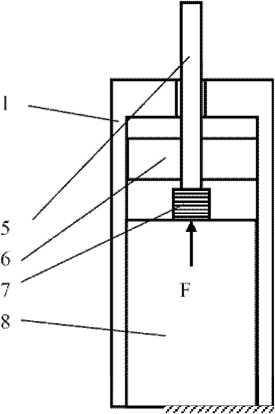
[0020] like figure 1 As shown, this embodiment includes: a sleeve 1, an output rod 5, a guide mechanism 6, a thrust piezoelectric sensor body 7 and a telescopic drive device 8, wherein: the guide mechanism 6 is movably arranged in the sleeve 1, and the thrust piezoelectric sensor The sensing body 7 is fixedly connected with the telescopic driving device 8 , the middle part of the output rod 5 is fixedly connected with the guide mechanism 6 and the end is connected with the thrust piezoelectric sensing body 7 .
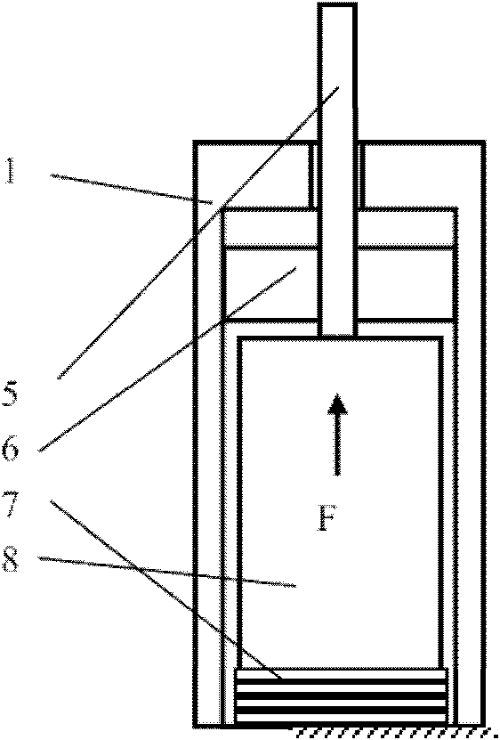
[0021] like figure 2 As shown, the thrust piezoelectric sensing body 7 and the telescopic driving device 8 can also exchange positions.
[0022] The working process of the present embodiment is: when the telescopic drive device 8 is externally excited, such as the magnetostrictive drive device 8 is excited by an external electromagnetic field, it will be deformed and elongated. Because the lower end of the telescopic drive device 8 is fixed, its elongation The amoun...
Embodiment 2
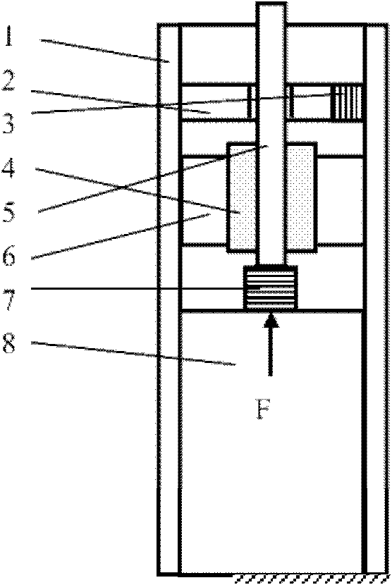
[0025] like image 3 As shown, the sleeve 1 described in this embodiment is provided with a magnetostrictive body 2 and a displacement piezoelectric sensor 3, wherein: the magnetostrictive body 2 and the displacement piezoelectric sensor 3 are connected in series to the sleeve 1 and parallel to the guide mechanism 6, the magnetostrictive body 2 is in sliding contact with the output rod 5.
[0026] A permanent magnet 4 is arranged between the output rod 5 and the guide mechanism 6 .
[0027] The working process of the present embodiment is: when the telescopic drive device 8 is externally excited, such as the magnetostrictive drive device 8 is excited by an external electromagnetic field, it will be deformed and elongated. Because the lower end of the telescopic drive device 8 is fixed, its elongation The amount will be transmitted to the output rod 5 through the thrust piezoelectric sensing body 7 fixedly connected with it, and the output rod 5 will drive the guide mechanism ...
Embodiment 3
[0030] like Figure 4 As shown, a bias permanent magnet 9 is provided between the magnetostrictive body 2 and the housing 1 .
[0031] The working process of this embodiment is the same as that of Embodiment 2, except that a bias permanent magnet 9 is arranged between the magnetostrictive body 2 and the housing 1 structurally. The bias permanent magnet 9 has the capability of pre-biasing the magnetostrictive body 2 to its linear expansion and contraction range. Under this structure, the driving displacement sensing that can be realized has higher sensitivity and more accurate displacement sensing.
PUM
 Abstract
Description
Claims
Application Information
 - R&D
- Intellectual Property
- Life Sciences
- Materials
- Tech Scout
- Unparalleled Data Quality
- Higher Quality Content
- 60% Fewer Hallucinations
Browse by: Latest US Patents, China's latest patents, Technical Efficacy Thesaurus, Application Domain, Technology Topic, Popular Technical Reports.
© 2025 PatSnap. All rights reserved.Legal|Privacy policy|Modern Slavery Act Transparency Statement|Sitemap|About US| Contact US: help@patsnap.com


