
Direct-current offset calibration method and device

A technology of DC bias and calibration device, which is applied in the field of zero-IF reception to achieve the effect of cost reduction and simple circuit structure

Active Publication Date: 2011-07-13
COMBA TELECOM SYST CHINA LTD
View PDF4 Cites 17 Cited by
  • Summary
  • Abstract
  • Description
  • Claims
  • Application Information

AI Technical Summary

Problems solved by technology

[0004] However, the zero-IF receiving system faces many new technical challenges

Method used


Image

  • Direct-current offset calibration method and device
  • Direct-current offset calibration method and device
  • Direct-current offset calibration method and device

Examples


Embodiment approach

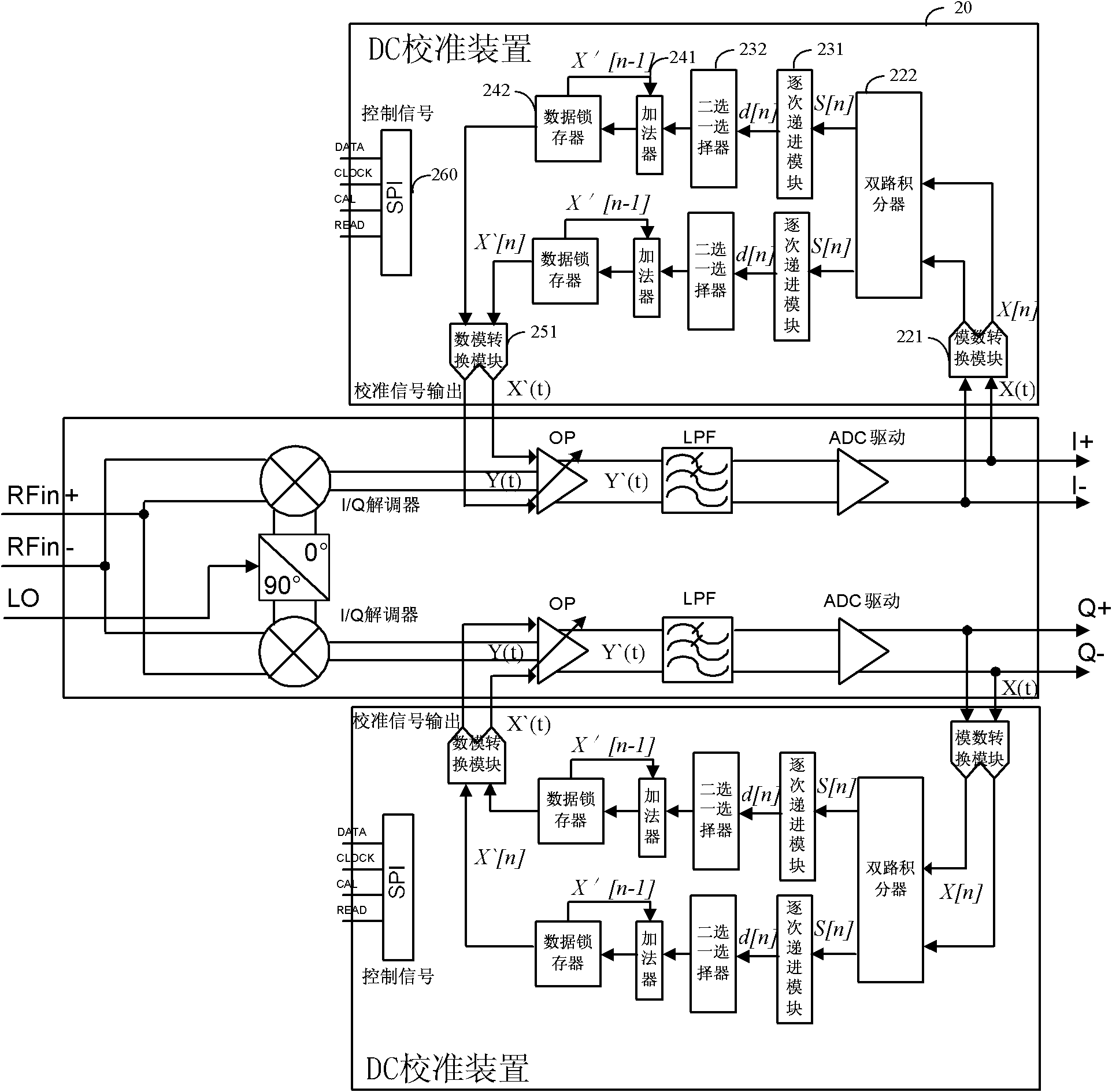
[0105] As a preferred implementation, the DC offset calibration device is provided with at least the following four pins:

[0106] The enable pin is used to input a control signal to trigger the DC offset calibration device to start or stop the DC offset calibration;

[0107] A clock pin, used to input the standard reference clock of the DC offset calibration device;

[0108] a read pin for reading data from said DC bias calibration device;

[0109] A data pin for inputting and outputting application data to the DC bias calibration device.

[0110] Through the enable pin, a control signal can be sent to the DC offset calibration device to force it to start or stop DC offset calibration; the clock pin can provide a standard reference clock to the DC offset calibration device , to ensure the synchronous operation of each circuit module; through the read pin and the data pin, data can be input or read from the DC offset calibration device.

[0111] Preferably, the above four p...


PUM


Abstract

The invention provides a direct-current offset calibration method and device, wherein the method comprises the following steps: judging whether the output of a zero intermediate frequency receiving system is in accordance with a convergence condition by feeding back an analogue base-band differential voltage output by the zero intermediate frequency receiving system; and calibrating the base-band signal of the zero intermediate frequency receiving system. In the process of calibration, the adjust values calibrated every time are set by using a gradually stepping manner in descending order, and then the adjust values calibrated every time are superimposed so that the whole direct-current offset calibration process has the effect of firstly roughly adjusting and then transiting to micro-adjustment gradually; and the direct-current offset calibration can be realized quickly and accurately in order to meet the convergence condition. Moreover, the direct-current offset calibration is carried out on a time division duplex (TDD) zero intermediate frequency receiving system by using the non-receiving data time slot of the TDD zero intermediate frequency receiving system, so that the real-time performance of direct-current offset calibration is improved.

Description

technical field [0001] The invention relates to the field of zero-IF receiving technology, in particular to a DC offset calibration method and a DC offset calibration device for a ZIF receiving system. Background technique [0002] The zero-IF receiving system has the characteristics of small size, low cost and easy monolithic integration. It has become a very competitive structure in the radio frequency receiving system and has received extensive attention in the field of wireless communication. [0003] The zero-IF receiving system converts the RF signal into a baseband signal through a frequency conversion. Compared with the current popular high-frequency sampling receiving system, the main advantages are as follows: (1) It can save the digital frequency converter and high-speed AD, and reduce the requirements for the digital part of the circuit. . (2) Since the zero-IF solution does not require a high-speed digital sampling clock, it can reduce the influence of high-spe...

Claims


Application Information

Patent Timeline
IPC IPC(8): H04L25/06H04B1/30
Inventor 刘畅远张凯
Owner COMBA TELECOM SYST CHINA LTD
Features
  • Generate Ideas
  • Intellectual Property
  • Life Sciences
  • Materials
  • Tech Scout
  • Unparalleled Data Quality
  • Higher Quality Content
  • 60% Fewer Hallucinations
Learn More