Sludge dryer with increased retention time

A technology of sludge drying and residence time, applied in the fields of sludge drying, sludge treatment, sludge treatment, etc., can solve the problems of heat loss and difficulty in recovering heat, so as to reduce the treatment cost and time, and improve the reuse value. Effect

Inactive Publication Date: 2011-07-13
SEWON INDUSTIRIES
View PDF0 Cites 20 Cited by
  • Summary
  • Abstract
  • Description
  • Claims
  • Application Information

AI Technical Summary

Problems solved by technology

[0003] The biggest feature of the above-mentioned method is that the process of horizontal movement and downward movement is continuously and repeatedly performed, and in the case of supplying hot air for drying the above-mentioned sludge, there is a possibility of separately forming hot air for all screw conveyors arranged in multiple layers. Disadvantages of supply port
[0004] That is, the above-mentioned disadvantage is that, even in the case of using electric heat or using steam, all equipment needs to be provided in each screw conveyor, so that all the screw conveyors that deliver the sludge to each side are treated with uniform a

Method used


Image

  • Sludge dryer with increased retention time
  • Sludge dryer with increased retention time
  • Sludge dryer with increased retention time

Examples


Example Embodiment

[0037] The configuration and structure of the present invention will be described in detail below with reference to the drawings.
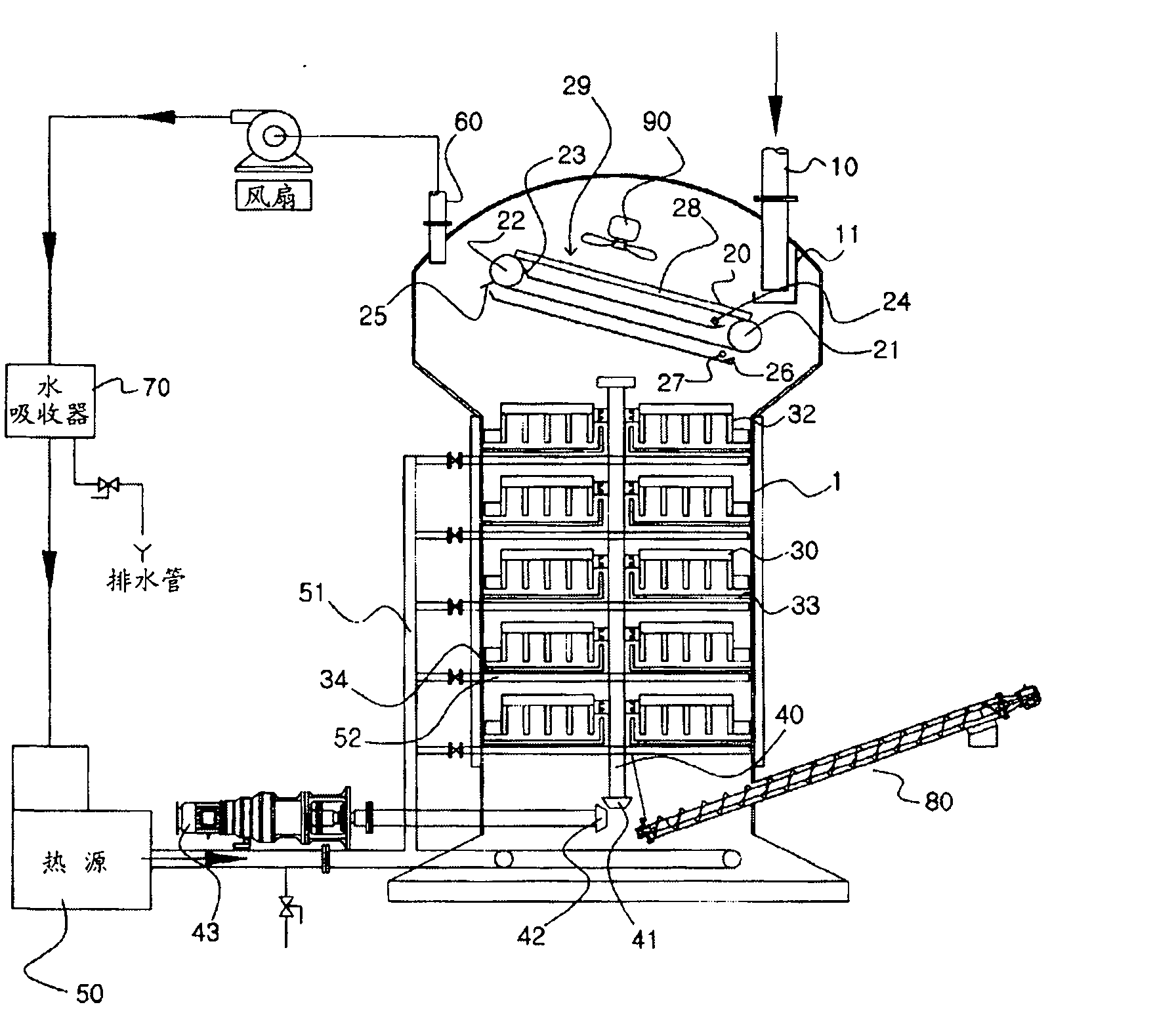
[0038] figure 1 It represents the alternate sludge drying device of the present invention with increased residence time. A cylindrical body 1 is formed on the device, and a space is formed inside to allow the sludge to be put in and dried, and through an inlet 10 formed on the upper part of the body to introduce sludge from the outside, the sludge Supply to the main body 1.

[0039] The sludge supplied through the inlet 10 is supplied to a wire box (Wire box) 11 provided below the inlet, and the sludge supplied to the wire box overflows from the wire box, and the sludge overflowing the wire box is supplied to In addition to water 29.

[0040] However, the above-mentioned wire box may not be used, and the sludge may be directly supplied to the water separator 29 from the inlet 10. The above-mentioned water eliminator 29 includes: two pulleys 21, 22, wh...


PUM


Abstract

The present invention relates to a sludge dryer with increased retention time, comprising a main body having a space formed therein for the insertion and drying of sludge; an input formed in the upper part of the main body to introduce the sludge into the main body from the outside; a plurality of drying plates that are installed vertically in a multistage manner to dry the sludge by receiving the sludge introduced by the input and retaining the sludge; a shaft installed in the vertical direction at the center of the main body and rotated by the power transmitted from a central motor; one or more moving scrapers installed in the radial direction on the respective drying plates, and having a plurality of movers that are connected to the shaft and obliquely coupled at a predetermined interval so that the sludge supplied to the drying plates is gradually moved to the central part or the outer peripheral part of the drying plates while rotating; drop grooves that are respectively formed in an alternating fashion in the central part and the outer peripheral part in the upper and lower drying plates that are installed in a multistage manner such that sludge moved to the central part or the outer peripheral part of the drying plates can be dropped to a lower stage by the movers; and a supply pipe connected to a heat source via a hot air pipe and installed at the lower side of each drying plate so as to supply heat to the respective drying plates.

Description

technical field [0001] The present invention relates to a sludge drying device, and more specifically relates to a sludge drying device with increased residence time which improves initial water removal efficiency while increasing the residence time of sludge. Background technique [0002] The biggest feature of the sludge drying device is that the above-mentioned sludge flow moves in a curved shape, and the drying process is realized while passing through a screw conveyor. After receiving the sludge discharged from the above-mentioned screw conveyor, it is sent to the Conveying in the opposite direction while drying, this process is repeated several to dozens of times, thereby drying the sludge. [0003] The biggest feature of the above-mentioned method is that the process of horizontal movement and downward movement is continuously and repeatedly performed, and in the case of supplying hot air for drying the above-mentioned sludge, there is a possibility of separately form...

Claims


Application Information

Patent Timeline
IPC IPC(8): C02F11/12C02F11/13
CPCC02F11/12F26B2200/18F26B17/003C02F11/13C02F11/121C02F2201/002C02F2303/10Y02W10/20
Inventor 崔洛云
Owner SEWON INDUSTIRIES
Why Eureka
Try Eureka