
Mechanical cleaning device for product oil tank

A technology for mechanical cleaning and oil tanks, applied in the field of mechanical devices, to achieve the effect of ensuring safety and small equipment

Active Publication Date: 2011-07-20
CHINA OIL HBP SCI & TECH CO LTD +1
View PDF6 Cites 16 Cited by
  • Summary
  • Abstract
  • Description
  • Claims
  • Application Information

AI Technical Summary

Problems solved by technology

[0003] The purpose of the present invention is to provide a mechanical cleaning device for finished oil tanks in order to overcome the many disadvantages of conventional manual cleaning and make up for the shortcomings of current cleaning equipment in process design. cleaning

Method used

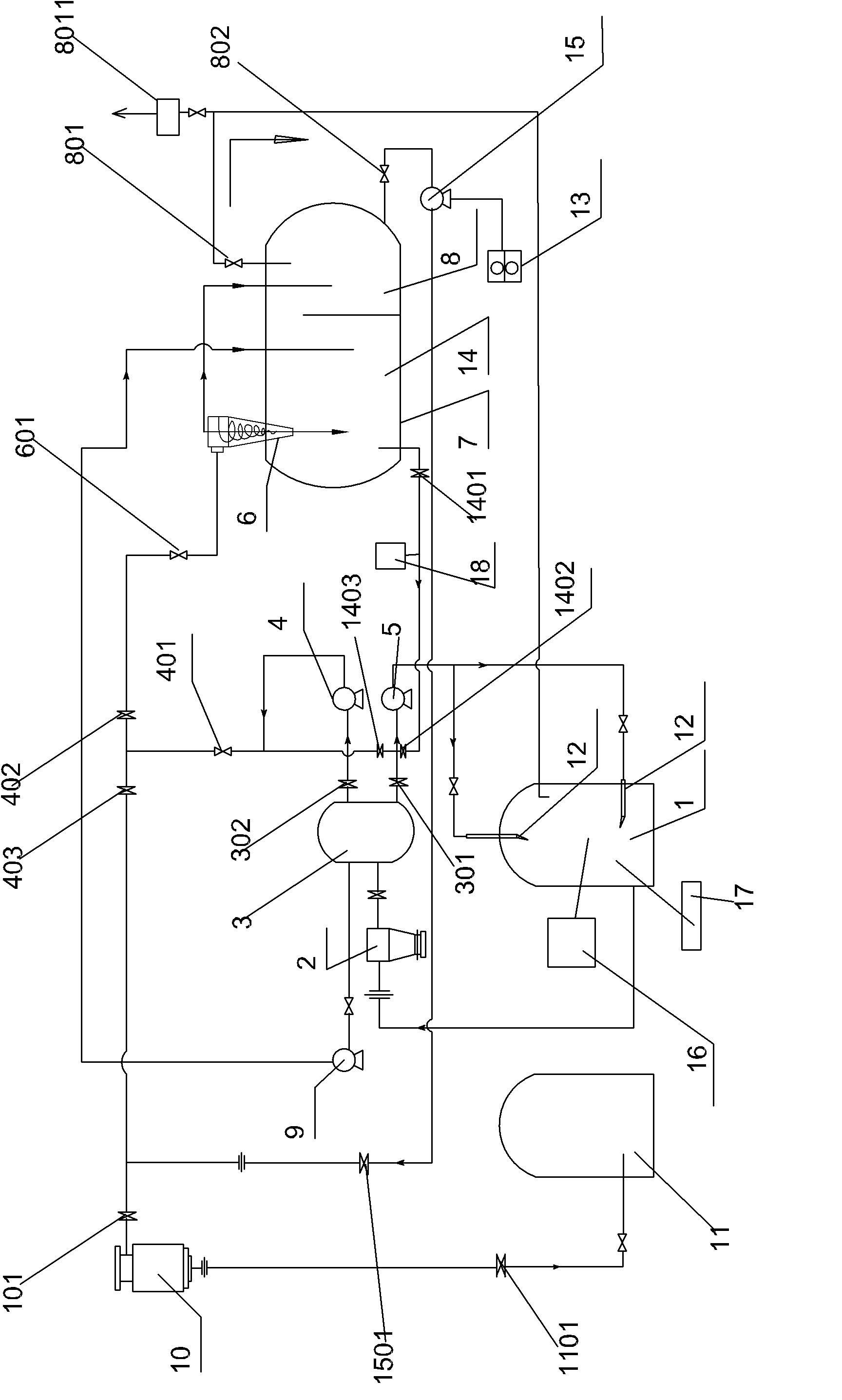
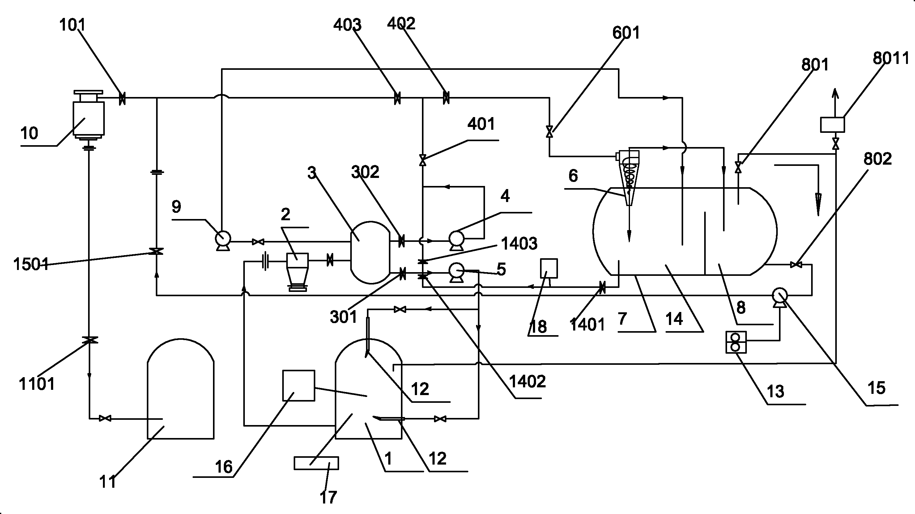

Image

  • Mechanical cleaning device for product oil tank
  • Mechanical cleaning device for product oil tank

Examples


Embodiment

[0024] A mechanical cleaning device for finished oil tanks, comprising: an oil tank to be cleaned 1, a water chamber 14, and a cleaning pump, the oil tank to be cleaned 1 communicates with a vacuum suction tank 3 through a filter 2 through a valve, and the vacuum suction tank 3 divided into three routes: the first route is connected to the cleaning pump 5 and at least one sprayer 12 in the oil tank 1 to be cleaned in turn through the valve 301; the second route is connected to the recovery pump 4 in turn through the valve 302, and the recovery pump 4 is divided into two routes through the valve 401 One way is connected to the precision filter 10 and the valve 1101 to the recovery oil tank 11 through the valve 403 and the valve 101 in turn; the other way is connected to the oil-water separation tank 7 through the valve 402, the valve 601 and the cyclone separator 6; 1. The vacuum pump 9 is connected to the oil-water separation tank 7; the upper pipe of the oil-water separation t...


PUM


Abstract

The invention provides a mechanical cleaning device for a product oil tank. The mechanical cleaning device comprises a to-be-cleaned oil tank, a water chamber, and a washing pump. The mechanical cleaning device for the product oil tank is characterized in that the to-be-cleaned oil tank is orderly communicated with a filter and a vacuum suction tank, and the vacuum suction tank is divided into three routes, wherein the first route is orderly communicated with the washing pump, at least one ejector, and the to-be-cleaned oil tank; the second route is communicated with a recovery pump and divided into two routes, wherein one route is orderly communicated with an ultrafilter and a recovered oil tank, and the other route is communicated with an oil-water separation tank by a cyclone separator; and the third route is orderly communicated with a vacuum pump and the oil-water separation tank; an upper pipe of the oil-water separation tank is divided into two routes, wherein one route is connected with an evacuation pipe through a flame arrester, and the other route is connected with the to-be-cleaned oil tank; a lower pipe of the oil-water separation tank is divided into two routes through a valve and a membrane pump, wherein one route is communicated with the recovered oil tank through the ultrafilter, and the other route is communicated with an air compressor; and a water pipe of the oil-water separation tank is divided into two routes through a valve, wherein one route is communicated with the cleaning pump, and the other route is communicated with the oil-water separation tank by the cyclone separator. The mechanical cleaning device can efficiently, safely and conveniently clean the to-be-cleaned oil tank.

Description

technical field [0001] The invention relates to a mechanical device for automatic cleaning of small oil storage tanks, which is applied to cleaning mechanical devices for oil tanks to be cleaned in various oil depots and stations in the petroleum and petrochemical industry, in particular to a mechanical cleaning device for finished oil tanks. Background technique [0002] With the development of society and the improvement of economic level, society has higher and higher requirements for energy, and the volume of oil tanks to be cleaned for various applications, reserves, strategic crude oil and refined oil has increased rapidly. According to incomplete statistics, only domestic oil There are tens of thousands of large and small oil storage tanks in the petrochemical system, and a large number of oil tanks to be cleaned brings a lot of cleaning workload. At present, PetroChina and Sinopec's product oil tanks, chemical raw material tanks and aviation oil tanks are usually cle...

Claims


Application Information

Patent Timeline
IPC IPC(8): B08B9/093
Inventor 黄松白明垠黄永康张维
Owner CHINA OIL HBP SCI & TECH CO LTD
Learn More