Main shaft knife loosening and unloading mechanism

A spindle and knife loosening technology, applied in metal processing machinery parts, clamping, support and other directions, can solve the problems of destroying the rotation accuracy of the spindle bearing and reducing the service life of the bearing, so as to prolong the service life, improve the stress condition, and improve the maintenance sexual effect

Inactive Publication Date: 2011-07-20
ZHONGJIE MACHINE TOOL
View PDF14 Cites 13 Cited by
  • Summary
  • Abstract
  • Description
  • Claims
  • Application Information

AI Technical Summary

Problems solved by technology

[0002] At present, the spindle loosening mechanism of domestic machining centers and CNC milling machines is not designed with an unloading mechanism. The axial force generated when the spindle frequently releases the clamping tool directly acts on the bearing (about 15000N ~ 20000N), which destroys the rotation accuracy of the spindle bearing. , reducing the service life of the bearing

Method used


Image

  • Main shaft knife loosening and unloading mechanism
  • Main shaft knife loosening and unloading mechanism

Examples


Embodiment Construction

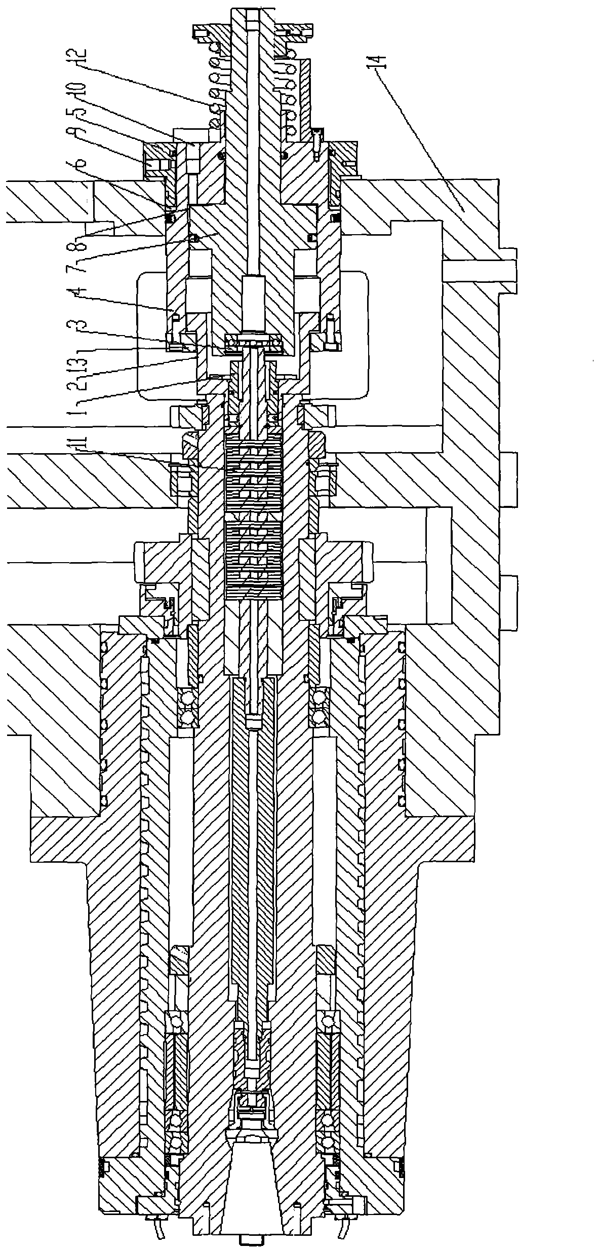
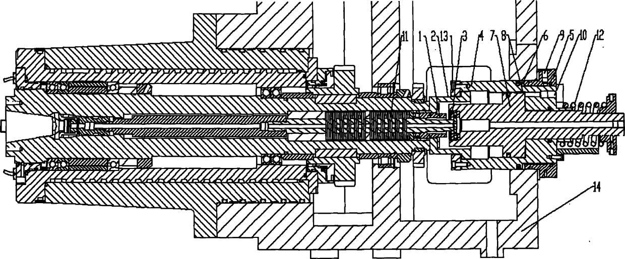
[0009] The structure of the spindle tool unloading mechanism, such as figure 1 As shown, it is characterized in that a gland 2 for unloading is fixed on the rear end of the main shaft, the nut 1 is fixed on the broach rod, the thrust bearing 3 of the loosening structure is fixed on the front end of the piston 7, and the piston 7 is placed in the cylinder 4 , the unloading plate 13 fixed with the cylinder body 4 is placed on the upper surface of the boss of the gland 2 to form an overlap, the cylinder liner 5 is fixedly installed on the headstock 14, and is in the same installation hole of the unloading mechanism as the cylinder body 4 . The unloading mechanism mounting hole and the spindle mounting hole are processed on the spindle box 14; the cylinder body 4, the cylinder liner 5 and the unloading mechanism mounting hole on the spindle box 14 jointly form an anti-closed oil chamber 6, and the outer circumference of the tail end of the piston 7 is connected to the cylinder bod...


PUM


Abstract

The invention provides a main shaft knife loosening and unloading mechanism. The mechanism is characterized in that a gland is coaxially fixed on the rear end face of a main shaft; a nut is fixed on a broach rod; a thrust bearing of a knife loosening structure is fixed at the front end of a piston; the piston is arranged in a cylinder body; an unloading disc fixed together with the cylinder body is arranged on the upper surface of the boss of the gland to form an overlap joint; a cylinder sleeve is fixed on a headstock, and is arranged in the same mounting hole together with the cylinder body; a spring is arranged between the periphery of the tail end of the piston and the cylinder body; the cylinder body, the cylinder sleeve and an unloading mechanism installation hole on the headstock jointly form a negative closed oil cavity; an axial oil injection port is processed on the rear part of the cylinder body, and forms a positive closed oil cavity together with the piston; and a radial oil injection port is processes at the tail end of the cylinder sleeve. By utilizing the main shaft knife loosening and unloading mechanism, the main shaft bearing is protected from axial force impact during knife loosening, so that the stress condition of the main shaft bearing is improved, the maintenance of rotation accuracy of the main shaft bearing is improved, and the service life of the bearing is prolonged.

Description

technical field [0001] The invention relates to improving the stress condition of the main shaft bearing when the main shaft of the machining center and the numerical control milling machine is loosened, improving the maintenance of the rotation accuracy of the main shaft bearing and prolonging the service life of the bearing. Background technique [0002] At present, the spindle loosening mechanism of domestic machining centers and CNC milling machines is not designed with an unloading mechanism. The axial force generated when the spindle frequently releases the clamping tool directly acts on the bearing (about 15000N ~ 20000N), which destroys the rotation accuracy of the spindle bearing. , reduce the service life of the bearing. [0003] As the market has higher and higher requirements for the precision, reliability and service life of CNC machine tools, the spindle, as an important part of machine tools, has become more and more important to maintain its rotation accuracy...

Claims


Application Information

Patent Timeline
Patent Type & Authority Applications(China)
IPC IPC(8): B23Q3/157
Inventor 刘春时李焱侯沿星戚远大张凯楚文龙徐吉存张健高柏宏王迪张伟侯春华王亮化春雷贾歆莹张明洋刘旭谢志坤罗和平孙涛孔令友
Owner ZHONGJIE MACHINE TOOL
Why Eureka
Try Eureka