Positioning device, sticking system and sticking method

A positioning device and glue technology, applied in the direction of sustainable manufacturing/processing, electrical components, climate sustainability, etc., can solve the problem of affecting the quality of silicon blocks, high production costs, and the center alignment of the center of the silicon rod and the crystal support Difficulties and other problems to achieve the effect of reducing production costs and ensuring quality

Inactive Publication Date: 2011-07-20
ZHEJIANG YUHUI SOLAR ENERGY SOURCE
View PDF1 Cites 6 Cited by
  • Summary
  • Abstract
  • Description
  • Claims
  • Application Information

AI Technical Summary

Problems solved by technology

[0005] However, in the prior art, it is still a very difficult technical problem to align the center of the silicon rod with the center of the crystal support after controlling the gluing, that is, there is no better gluing system to realize the gluing The center of th

Method used


Image

  • Positioning device, sticking system and sticking method
  • Positioning device, sticking system and sticking method
  • Positioning device, sticking system and sticking method

Examples


Example Embodiment

[0045] Embodiment one

[0046] As mentioned in the background technology section, it is still a very difficult technical problem to align the center of the single crystal silicon rod (silicon rod for short) with the center of the crystal support after controlling the glue in the prior art. If the center of the rod and the center of the crystal holder are not aligned, the quality of the subsequently formed silicon block will not meet the requirements, and then the silicon block will be scrapped, thereby increasing the production cost.

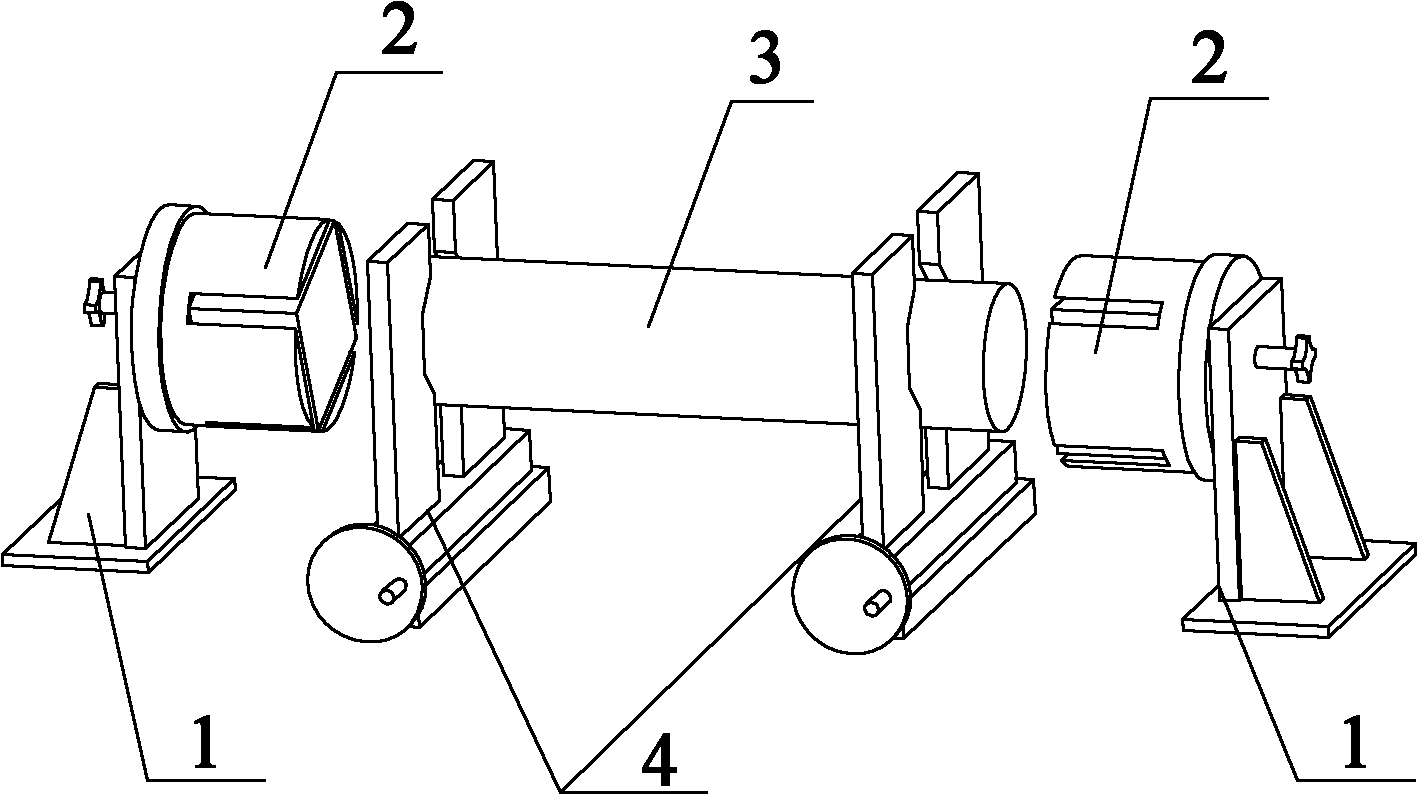
[0047] refer to figure 1 , figure 1 It is a structural schematic diagram of a positioning device in the prior art. The single crystal silicon rod 3 is shown in the figure, and the clamping mechanism 4 for clamping the single crystal silicon rod 3 has two clamping mechanisms 4, which respectively clamp the two ends of the single crystal silicon rod 3; The silicon rod 3 has two end faces, and one side of each end face is provided with a crystal...

Example Embodiment

[0054] Embodiment two

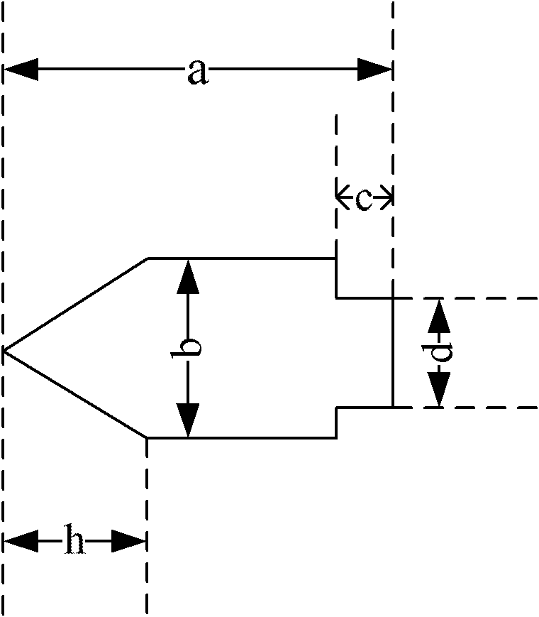
[0055] The present invention also provides a positioning device, which is used for aligning the center of the single crystal silicon rod with the center of the crystal support before bonding the single crystal silicon rod and the crystal support. The positioning device includes: a clamping mechanism for clamping a single crystal silicon rod; a crystal holder fixing frame for fixing the crystal holder; a positioning pin installed at the center of the crystal holder at one end, and the other end of the positioning pin is a cone.

[0056] In this embodiment, one end of the positioning pin installed in the center of the crystal holder is provided with a thread, and the center of the crystal holder is provided with a threaded hole, and one end of the positioning pin is installed in the threaded hole in the center of the crystal holder in the form of a thread.

[0057] During the specific implementation process, the clamping mechanism is adjusted so that the ...

Example Embodiment

[0058] Embodiment three

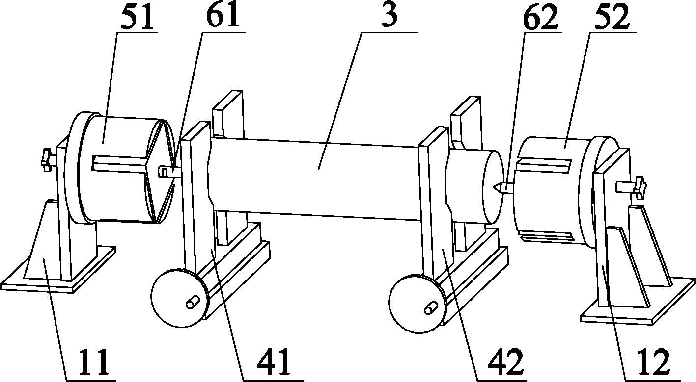
[0059] The present invention also provides a kind of viscose method, with reference to Figure 4 , Figure 4 It is a schematic flow chart of the viscose method provided by the present invention. combine figure 2 , the method specifically includes the following steps:

[0060] Step S1: Install a positioning pin at the center of the crystal support on the crystal support holder, and one end of the positioning pin exposed outside the center of the crystal support is a cone.

[0061] In the specific implementation process, at first the first crystal holder 51 is fixed on the first crystal holder holder 11, the second crystal holder 52 is fixed on the second crystal holder holder 12, the first crystal holder 51 and the second crystal holder 52 correspond to the two end surfaces of the single crystal silicon rod 3 respectively. Then a first alignment pin 61 is installed at the center of the first crystal holder 51 , and a second alignment pin 62 is in...


PUM

PropertyMeasurementUnit
Bottom diameteraaaaaaaaaa
Thread lengthaaaaaaaaaa
Diameteraaaaaaaaaa

Abstract

The embodiment of the invention discloses a positioning device, a sticking system and a sticking method. The sticking system and the sticking method are used for sticking a single crystal silicon rod and a crystal support, and the sticking system comprises the positioning device and a sticking device, wherein the positioning device comprises a clamping mechanism for clamping the single crystal silicon rod, a crystal support fixing frame for fixing the crystal support and a positioning pin, one end of the positioning pin is mounted at the center of the crystal support, the other end of the positioning pin is in the shape of a cone. By adopting the positioning device, the sticking system and the sticking method, the center of the single crystal silicon rod and the center of the crystal support can be strictly aligned before sticking the single crystal silicon rod with the crystal support, thereby further ensuring that the center of the single crystal silicon rod and the center of the crystal support can be strictly aligned after completing the follow-up sticking work, being conductive to ensuring the quality of silicon blocks after square cutting, further reducing the number of the scrapped silicon blocks, and reducing the production cost.

Description

technical field [0001] The invention relates to the technical field of the photovoltaic industry, and more specifically, to a positioning device, a gluing system and a gluing method. Background technique [0002] In today's energy shortage and increasingly serious environmental pollution, the photovoltaic industry, which uses solar energy and is green and environmentally friendly, undoubtedly has broad development prospects, which makes more and more companies and enterprises increase investment in it. [0003] The production chain of the photovoltaic industry includes: polycrystalline silicon→monocrystalline silicon→cells→cell modules→application systems, etc. Among them, the monocrystalline silicon made from polycrystalline silicon needs to go through the Czochralski process, and the resulting monocrystalline silicon is generally cylindrical, so it is called a single crystal silicon rod (hereinafter referred to as a silicon rod). In the subsequent process, the silicon rod ...

Claims


Application Information

Patent Timeline
IPC IPC(8): H01L31/18H01L21/68H01L21/683H01L21/00
CPCY02P70/50
Inventor 刘学杨长剑秦洪强陈斯奇
Owner ZHEJIANG YUHUI SOLAR ENERGY SOURCE
Why Eureka
Try Eureka