Cutter for chamfering

A technology of milling cutters and milling devices, which is applied in the direction of milling cutters, manufacturing tools, milling machine equipment, etc., can solve the problems of shortened service life of milling cutters, increased cutting load, and difficulty in working, so as to achieve simple milling work, reduce cutting load, and improve The effect of processing power

Inactive Publication Date: 2011-07-20
金 容范
View PDF0 Cites 8 Cited by
  • Summary
  • Abstract
  • Description
  • Claims
  • Application Information

AI Technical Summary

Problems solved by technology

If the chips generated during work are too long, they will wind up on the milling machine rotating at high speed, making it difficult to work
Furthermore, if the small chips are not quickly discharged, the cutting load during work will be increased, which will not only make the work difficult, but also shorten the service life of the milling tool
[0005] Therefore, in order to solve the chips that occur during milling work, attempts have been made to form discharge grooves, etc. on the milling tool, but the effect is not great

Method used


Image

  • Cutter for chamfering
  • Cutter for chamfering
  • Cutter for chamfering

Examples


Embodiment Construction

[0021] The present invention will be described in detail below with reference to the accompanying drawings.

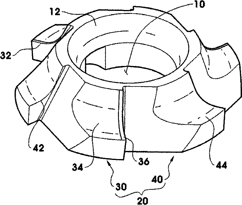
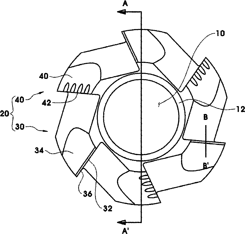
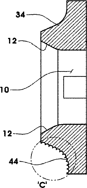
[0022] figure 1 is an oblique view of a milling tool according to an embodiment of the present invention, figure 2 for figure 1 Front view of the milling tool shown, image 3 for figure 2 Sectional view of the milling tool shown on the cutting line A-A’, Figure 4 for figure 2 Rear view of the milling tool shown.

[0023] Such as figure 1 with 2 As shown, the milling tool of the present invention is provided with a through hole 10 in the center, so that the connecting bolt penetrates and connects to the rotating shaft, and forms a gear shape in which a plurality of cutting inserts 20 are radially provided around the through hole 10 . At this time, the number of cutting inserts 20 may be 4 to 8, and is 6 in this embodiment.

[0024] Such as figure 1 with 3 As shown, each cutting insert 20 has a shape that protrudes toward the center as a whole.

[0025] A...


PUM


Abstract

The present invention aims to provide a cutter for chamfering that improves the ability to deal with the chips created during the chamfering work and thus reduces cutting load. To achieve the above objective, an aspect of the present invention provides a cutter for chamfering, which may be connected to a rotating shaft so as to rotate and trim an edge of an object. The cutter may have a through-hole (10) formed in its center, so that a fastening bolt inserted through the through-hole (10) may connect the cutter to one end of the rotating shaft; the cutter may be shaped as a cogwheel having a multiple number of cutting blades (20) that are positioned radially about the through-hole (10) and formed as an integrated body; the cutting blades (20) may be shaped to generally protrude towards the center, with each of the blades including a blade portion (32, 42), which is formed in an end part of the cutting blade (20) in a direction of rotation, and an arc (34, 44) portion, which forms a concave arced surface; and the cutting blades (20) may include finish-grinding blades (30) and rough- grinding blades (40) that are positioned alternately, the finish-grinding blades (30) having smooth surfaces on the arc portions (34), and the rough-grinding blades (40) having rough surfaces on the arc portions (44). According to the present invention, the ability of the chamfering cutter to handlechips can be improved, and the cutting load can be lowered, so that the chamfering work can be facilitated, the work speed can be increased, and the durability of the chamfering cutter can be prolonged.

Description

technical field [0001] The present invention relates to a milling tool, and more particularly to a milling tool mounted on a milling tool utilizing rotational force. Background technique [0002] Generally, the work of cutting the edge or corner of a tool or workpiece to make a bevel or a circle is called milling work (chamfering or chamfering), and the machine used for this is called a milling machine. [0003] There are milling machines that perform milling work in various ways, but a typical method is to perform machining by rotating a milling tool mounted on the end of a rotary shaft. [0004] One problem with such mills utilizing rotational force is chips that occur during milling work. If the chips generated during work are too long, they will wind up on the milling machine rotating at high speed, making it difficult to work. Furthermore, if the small chips are not quickly discharged, the cutting load during operation is increased, so that not only the work is diffic...

Claims


Application Information

Patent Timeline
IPC IPC(8): B23C5/12
CPCB23C2210/088B23C5/12B23C2210/084B23C2220/605B23C3/12B23C5/02
Inventor 金容范
Owner 金 容范
Why Eureka
Try Eureka