Chemical metallurgical connecting method for heat pipe and radiating fins

A heat-dissipating fin and chemical metallurgy technology, applied in the field of heat-dissipating devices, can solve the problems of reduced production efficiency, easy change of fin position, insignificant reduction of thermal resistance, etc. Effect

Active Publication Date: 2013-04-03
NORTHWEST INSTITUTE FOR NON-FERROUS METAL RESEARCH
View PDF1 Cites 0 Cited by
  • Summary
  • Abstract
  • Description
  • Claims
  • Application Information

AI Technical Summary

Problems solved by technology

Applying solder paste and then brazing through heat treatment is a traditional chemical metallurgical method for connecting fins and heat pipes. If you first apply solder paste on the heat pipe and then insert the fins, because the fit gap between the fins and the heat pipe is small, The solder paste is easy to be squeezed out, resulting in insufficient application amount. If the fins are inserted on the heat pipe before applying the solder paste, the solder paste will be applied unevenly and the production efficiency will be significantly reduced.
The patent of invention with the publication number CN 101141867A discloses a chemical metallurgical method in which tin tubes are first inserted into the fins and then heat pipes are inserted, and then fins and heat pipes are connected through heat treatment. This method makes the fins and heat pipes If the fit gap is too large, the position of the fins is easy to change during the heat treatment process, especially because the thermal resistance is inversely proportional to the thermal conductivity and proportional to the thickness, the thermal conductivity of tin is relatively low and the increase in the thickness of the chemical metallurgical connection leads to an insignificant decrease in thermal resistance
The utility model with the authorized announcement number CN 2569532Y discloses a relatively small solder paste injection hole above the heat pipe perforation of the fin, injects solder paste into the injection hole after passing through the heat pipe, and then connects the fin to the heat pipe through heat treatment. A chemical metallurgical method, which can chemically metallurgically connect the fins and heat pipes with flanged fins and the fin spacing is equivalent to the height of the flanged flanges, but the high-power LED heat pipe fin radiator requires the fin spacing to be greater than the flanged edge height, and this method is difficult to realize the chemical metallurgical connection between the fins with large fin spacing and the heat pipe

Method used


Image

  • Chemical metallurgical connecting method for heat pipe and radiating fins
  • Chemical metallurgical connecting method for heat pipe and radiating fins
  • Chemical metallurgical connecting method for heat pipe and radiating fins

Examples


Embodiment 1

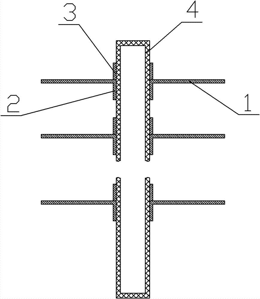
[0017] Such as figure 1 As shown, the cooling fin 1 with flange 2 is interspersed on the heat pipe 4, the outer diameter of the heat pipe 4 is 10.000mm, the tolerance is +0.000mm~+0.050mm, the inner diameter of the flange 2 is 10.000mm, the tolerance is + 0.100mm~+0.500mm, the outer diameter is 10.600mm, the height is 2.000mm, the thickness of the cooling fin 1 is 0.300mm; the tin ring 3 is inserted along the heat pipe on the side facing away from the flange 2, and the tin ring 3 is connected with the heat dissipation The fins 1 are in contact, so that a plurality of cooling fins 1 and tin rings 3 are socketed on the heat pipe repeatedly. The inner diameter of the tin ring 3 is 10.200mm, the outer diameter is 11.000mm, and the height is 4.000mm; then Place the socket piece in the heat treatment furnace along the downward direction of the flange 2, heat the tin ring 3 to melt into tin liquid, and the tin liquid penetrates into the matching gap between the flange 2 and the heat ...

Embodiment 2

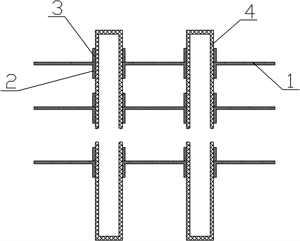
[0020] Such as figure 2 As shown, two heat pipes 4 are arranged in parallel, and the cooling fins 1 with flanging 2 are interspersed on the heat pipe 4. The outer diameter of the heat pipe 4 is 8.000mm, and the tolerance is +0.000mm~+0.050mm. is 8.000mm, the tolerance is +0.050mm~+0.200mm, the outer diameter is 8.600mm, the height is 2.000mm, and the thickness of the cooling fin 1 is 0.300mm; the tin ring 3 is inserted along the heat pipe on the side facing away from the flange 2, And the tin ring 3 is in contact with the heat dissipation fin 1, so that a plurality of heat dissipation fins 1 and the tin ring 3 are sleeved on the heat pipe repeatedly, and the inner diameter of the tin ring 3 is 8.100mm, and the outer diameter is 11.100mm , with a height of 3.000mm; then place the socket piece in a heat treatment furnace along the downward direction of the flange 2, heat the tin ring 3 to melt into tin liquid, and the tin liquid penetrates into the matching gap between the flan...

Embodiment 3

[0023] Such as image 3 As shown, two heat pipes 4 are arranged in parallel, and the cooling fins 1 with flanging 2 are interspersed on the heat pipes 4. 6.000mm, the tolerance is +0.050mm~+0.200mm, the outer diameter is 6.600mm, the height is 2.000mm, the thickness of cooling fin 1 is 0.300mm; And the tin ring 3 is in contact with the heat dissipation fin 1, so that a plurality of heat dissipation fins 1 and the tin ring 3 are sleeved on the heat pipe repeatedly, and the inner diameter of the tin ring 3 is 6.100mm, and the outer diameter is 13.200mm , with a height of 1.000mm; then place the socket piece in a heat treatment furnace along the downward direction of the flange 2, heat the tin ring 3 to melt into tin liquid, and the tin liquid penetrates into the matching gap between the flange 2 and the heat pipe 4 , to realize the chemical metallurgical connection between the heat pipe and the cooling fin; the width of the fitting gap is 2 μm to 25 μm; the distance between the...


PUM

PropertyMeasurementUnit
widthaaaaaaaaaa
widthaaaaaaaaaa
widthaaaaaaaaaa

Abstract

The invention discloses a chemical metallurgical connecting method for a heat pipe and radiating fins. The method comprises the following steps of: inserting a radiating fin with a turned edge into the heat pipe; inserting a tin ring into one side back to the turned edge along the heat pipe, making the tin ring contacted with the radiating fin, and repeating the process to sleeve a plurality of radiating fins and tin rings on the heat pipe to form a sleeved piece; and then putting the sleeved piece into a heat treatment furnace in the direction that the turned edges are downward, and melting the tin rings with heating, wherein the molten tin is infiltrated into the fit clearance between the turned edges and the heat pipe so as to realize chemical metallurgical connection of the heat pipe and the radiating fins. The insertion of the fins and the tin rings can be implemented on a streamline, the processing efficiency is high, the distance between the fins is not limited, the fit clearance between the turned edges of the fins and the heat pipe is small, the molten tin can be infiltrated under the combined action of gravity and capillary and filled into the fit clearance between the turned edges and the heat pipe to realize chemical metallurgical connection of the heat pipe and the radiating fins, and the connection thickness is low.

Description

technical field [0001] The invention belongs to the technical field of heat dissipation devices, and in particular relates to a chemical metallurgical connection method for heat pipes and heat dissipation fins. Background technique [0002] Heat dissipation is the "bottleneck" problem that restricts the industrialization of high-power LED lighting, and heat pipe fin radiators are one of the technical ways to solve the heat dissipation of high-power LEDs. In order to reduce the thermal resistance and improve the heat dissipation efficiency of the heat pipe fin radiator, a chemical metallurgical connection should be made between the fin and the heat pipe. Applying solder paste and then brazing through heat treatment is a traditional chemical metallurgical method for connecting fins and heat pipes. If you first apply solder paste on the heat pipe and then insert the fins, because the fit gap between the fins and the heat pipe is small, The solder paste is easy to be squeezed o...

Claims


Application Information

Patent Timeline
Patent Type & Authority Patents(China)
IPC IPC(8): B23K1/008H01L33/64
Inventor 杜明焕华云峰李争显杜继红王彦峰李宏战
Owner NORTHWEST INSTITUTE FOR NON-FERROUS METAL RESEARCH
Why Eureka
Try Eureka