Method and equipment for welding steel pipe and fins of H-type coal economizer used for boiler

A welding method and welding equipment technology, applied in the field of boiler manufacturing, can solve the problems of slow welding speed, reduced heat exchange efficiency, low production efficiency, etc., and achieve the effects of low processing accuracy requirements, improved heat exchange efficiency, and improved production efficiency.

Active Publication Date: 2015-07-08
HARBIN INST OF TECH
View PDF6 Cites 5 Cited by
  • Summary
  • Abstract
  • Description
  • Claims
  • Application Information

AI Technical Summary

Problems solved by technology

[0003] 1. Limited by the traditional welding process, the ribs can only be welded one by one, the welding speed is slow, the production efficiency is very low, and the manufacturing cost increases
[0004] 2. Affected by the traditional welding process, the distance between two fins is greater than 20mm, which limits the number of fins that can be welded on the steel pipe, reduces the finning ratio, and reduces the heat transfer area
[0005] 3. It only has good heat conduction effect at the solder joints, and the parts other than the solder joints are prone to virtual connections, resulting in increased thermal resistance and reduced overall heat transfer efficiency
[0006] 4. The fusion angle between the fin and the steel pipe is small, only about 140°, which reduces the contact area between the steel pipe and the fin and further reduces the heat transfer efficiency

Method used


Image

  • Method and equipment for welding steel pipe and fins of H-type coal economizer used for boiler
  • Method and equipment for welding steel pipe and fins of H-type coal economizer used for boiler
  • Method and equipment for welding steel pipe and fins of H-type coal economizer used for boiler

Examples


Embodiment 1

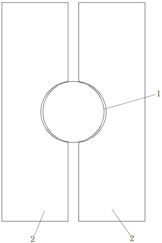
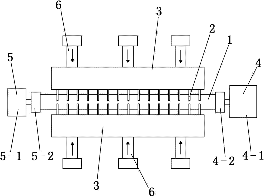
[0032] Embodiment 1: According to the manufacturing needs of an H-type economizer including a steel pipe 1, the motor drive system 4 includes a motor 4-1, an output shaft of a motor 4-1 and a three-jaw self-centering The chuck A4-2 is fixedly connected; the supporting device 5 includes a support 5-1 and a three-jaw self-centering chuck B5-2.

Embodiment 2

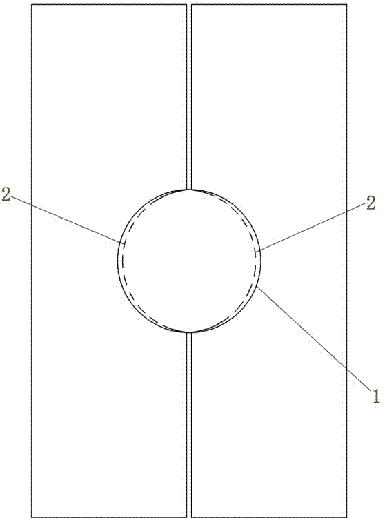
[0033] Embodiment 2: According to the manufacturing requirements of the H-type economizer including two steel pipes 1, the motor drive system 4 includes a motor 4-1, a motor 4-1 and two three-jaw self-centering chucks A4-2 connection, one of the three-jaw self-centering chucks A4-2 is fixedly connected with the output shaft of the motor 4-1, and the two three-jaw self-centering chucks A4-2 are connected through gears, so that the two three-jaw self-centering chucks The centering chuck A4-2 rotates synchronously; the support device 5 includes a support 5-1 and two three-jaw self-centering chucks B5-2, and the two three-jaw self-centering chucks B5-2 are respectively connected to the two The axis coincidence setting of a three-jaw self-centering chuck A4-2.


PUM


Abstract

The invention provides a method and equipment for welding a steel pipe and fins of an H-type coal economizer used for a boiler, belongs to the technical field of boiler manufacturing and solves the current problems existing in the welding of the steel pipe and the fins. The method for welding the steel pipe and the fins of the H-type economizer used for the boiler comprises the step of conducting friction welding to the multiple fins with the steel pipe simultaneously; the equipment for welding the steel pipe and the fins of the H-type economizer used for the boiler comprises two fin fixing dies, hydraulic telescopic devices, a motor driving system and a supporting device; the two fin fixing dies are arranged symmetrically, multiple grooves used for the fins to be inserted therein are formed in the inner surfaces of the two fin fixing dies correspondingly, the hydraulic telescopic devices are arranged at the outer sides of the two fin fixing dies respectively, the motor driving system is arranged at the outer side of one end of the two fin fixing dies, and the supporting device is arranged at the outer side of the other end of the two fin fixing dies. The method and equipment are used for welding of the H-type coal economizer.

Description

technical field [0001] The invention belongs to the technical field of boiler manufacturing, and in particular relates to a welding method and equipment for a steel pipe and fins of an H-type economizer for a boiler. Background technique [0002] In the current boiler manufacturing industry, H-type economizers with H-shaped fins welded outside steel pipes are more and more widely used because they can greatly improve heat exchange efficiency; at present, the welding of steel pipes and fins adopts the traditional Circumferential multi-point welding technology has the following disadvantages: [0003] 1. Limited by the traditional welding process, the ribs can only be welded one by one, the welding speed is slow, the production efficiency is very low, and the manufacturing cost increases. [0004] 2. Influenced by the traditional welding process, the distance between two fins is greater than 20mm, which limits the number of fins that can be welded on the steel pipe, reduces t...

Claims


Application Information

Patent Timeline
Patent Type & Authority Applications(China)
IPC IPC(8): B23K37/04
CPCB23K20/12B23K20/26B23K37/0443
Inventor 别如山纪晓瑜宋兴飞别海培陈佩房点李鹏坤顾文波
Owner HARBIN INST OF TECH
Why Eureka
Try Eureka