Liquid return circuit breaker valve

A technology of cut-off valve and valve core, which is used in mining equipment, earth-moving drilling, pillars/supports, etc., can solve problems such as leakage, and achieve the effect of prolonging service life and protecting biasing devices.

Inactive Publication Date: 2011-07-27
陈文才
5 Cites 0 Cited by

AI-Extracted Technical Summary

Problems solved by technology

[0003] For this reason, the technical problem to be solved by the present invention is that after the waterproof bag of the liquid return cut-off valve in the prior art is damaged, the med...

Method used

Described bias device is arranged in the waterproof bag 8 of sealing, can prevent described bias device from directly contacting with medium, thereby plays the effect of protecting described bias device, in the present embodiment, described ventilation The device is a branch ventilation pipe 9, the setting of the second one-way valve and the first one-way valve in the main and branch passages on the branch ventilation pipe 9 can ensure that the waterproof bag 8 can be normally compressed and recovered before it is worn out, and at the same time It can also ensure that after the w...

Abstract

The invention relates to a liquid return circuit breaker valve which comprises a shell, a valve core, a joint, a bias device, a fixed plate, a waterproof bag and a ventilation device, wherein the fixed plate is fixedly arranged in a through cavity at the tail part of the valve core, and a liquid through hole is molded along the circumferential direction of the fixed plate; the bias device is arranged in the sealed waterproof bag, one end of the bias device leans against the tail part of the valve core, and the other end of the bias device is fixedly arranged on the fixed plate; one end of theventilation device is inserted into the waterproof bag by the fixed plate, and the other end of the ventilation device extends outside the shell and communicated with the atmosphere; the ventilation device is also provided with a branch channel communicated with the tail end of the through cavity; the branch channel is internally provided with a first one-way valve which only allows the atmosphere to flow from the waterproof bag towards the tail end of the through cavity; and a main branch channel of the ventilation device communicated with the atmosphere is internally provided with a second one-way valve which only allows the atmosphere to flow towards the interior of the ventilation device. The liquid return circuit breaker valve is simple in structure, high in flow rate and long in service life.

Application Domain

Props/chocks

Technology Topic

EngineeringAtmosphere +3

Image

  • Liquid return circuit breaker valve
  • Liquid return circuit breaker valve

Examples

  • Experimental program(1)

Example Embodiment

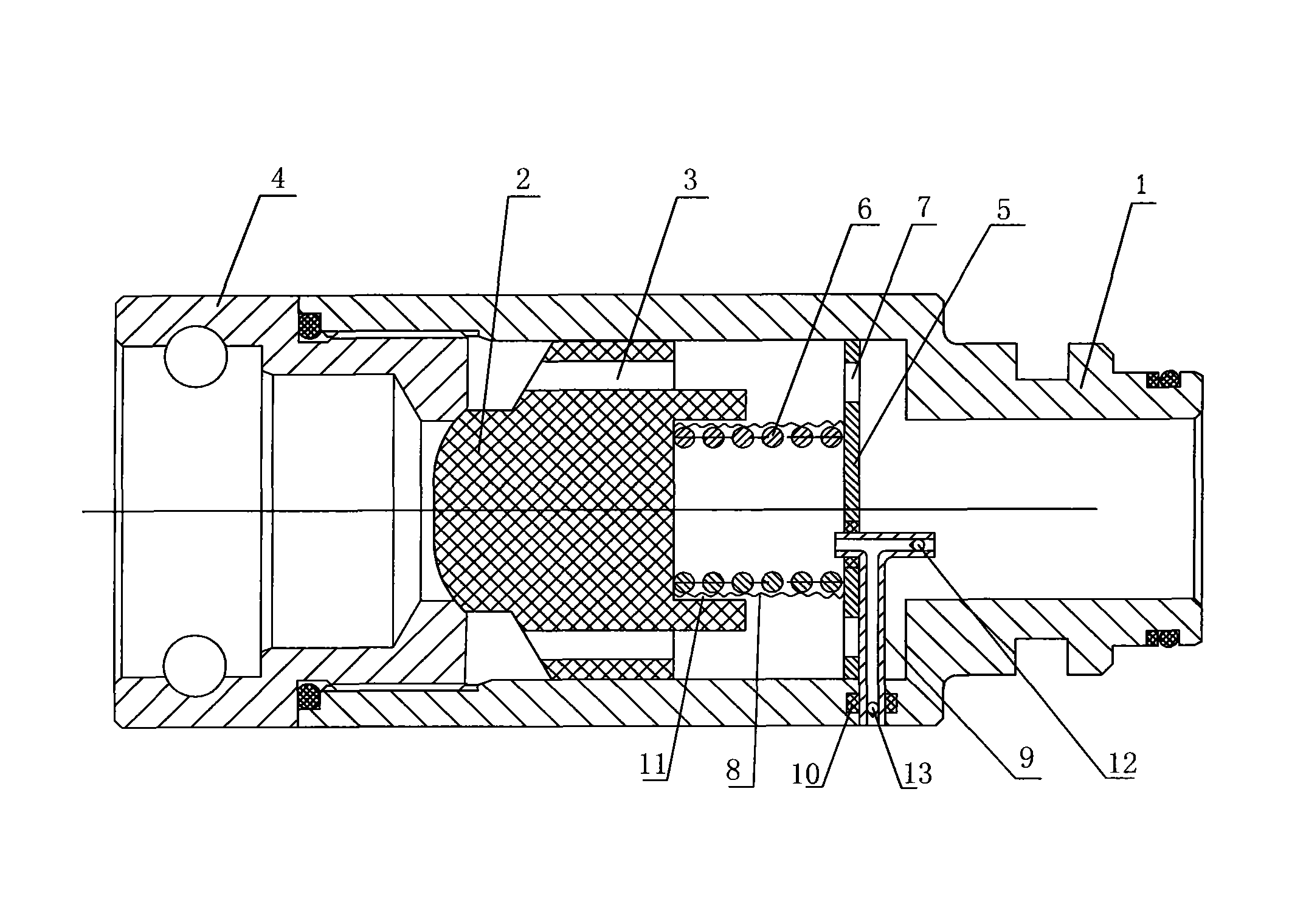
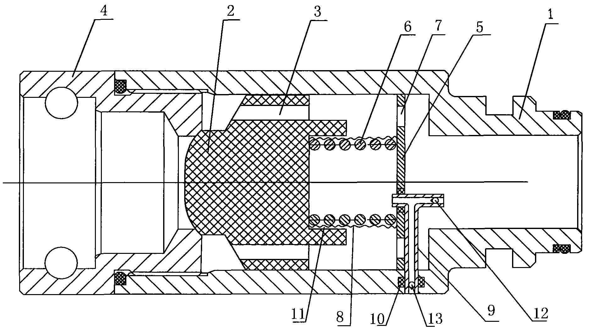
[0020] Such as figure 1 As shown, a liquid return shut-off valve of this embodiment includes a housing 1 in which a through cavity is formed;
[0021] The spool 2, the spool 2 is arranged in the through cavity, and the spool 2 is also provided with a liquid through hole 3 facing the tail of the spool;
[0022] The connector 4 is connected to the end of the housing 1 to which the head of the valve core points, and a through hole suitable for the insertion of the head of the valve core is formed in the connector 4, and the through hole of the connector 4 A contact seal is formed between the parts in contact with the head of the valve core;
[0023] A biasing device, the biasing device is arranged at the tail of the valve core, and by pressing the tail of the valve core, the head of the valve core abuts against the through hole;
[0024] The fixed plate 5 is fixedly arranged in the through cavity at the tail of the valve core, and the fixed plate 5 is circumferentially formed with a through hole 7;
[0025] Waterproof bag 8, the biasing device is arranged in a sealed waterproof bag 8, and one end of the biasing device is against the tail of the valve core, and the other end is fixed on the fixing plate 5;
[0026] A ventilation device, one end of the ventilation device is inserted into the waterproof bag 8 through the fixing plate 5, and the other end extends out of the housing 1 and communicates with the atmosphere;
[0027] The ventilation device is also provided with a branch channel communicating with the end of the through cavity, and the branch channel is provided with a first unit that only allows the waterproof bag 8 to circulate toward the end of the through cavity. The direction valve 12 is provided with a second check valve 13 in the main branch where the ventilation device communicates with the atmosphere, which only allows the atmosphere to circulate in the direction of the ventilation device.
[0028] The biasing device is arranged in the sealed waterproof bag 8, which can prevent the biasing device from directly contacting the medium, thereby protecting the biasing device. In this embodiment, the ventilation device is a The branch vent pipe 9, the second one-way valve and the first one-way valve in the main and branch channels on the branch vent pipe 9 can not only ensure the normal compression and recovery of the waterproof bag 8 before being worn, but also ensure that After the waterproof bag 8 is worn, the medium entering the branch vent tube 9 flows into the tail of the cavity of the housing 1 without flowing out of the valve body, which ensures that the liquid return shut-off valve can be used normally without leakage. A sealing ring 10 is provided between the fixing plate 5 and the vent pipe 9, and a sealing ring 10 is provided between the housing 1 and the vent pipe 9. A groove 11 is formed at the tail of the valve core, and one end of the biasing device is pressed into the groove 11. In this embodiment, the biasing device is a spring 6.
[0029] The working principle of the liquid return shut-off valve of the present invention:
[0030] (1) When the waterproof bag 8 is not damaged
[0031] The valve core 2 is opened when the liquid return shut-off valve is opened and the liquid is fed, causing the waterproof bag 8 to be compressed with the spring 6, and the gas in the waterproof bag 8 is discharged into the branch vent pipe, and the second one-way valve 13 in the main branch is closed and branched at the same time The first one-way valve in the channel is opened by the compressed gas and discharged into the end of the through cavity of the housing 1;
[0032] When the liquid return shut-off valve is closed, the valve core 2 is closed, causing the waterproof bag 8 to bulge with the recovery of the spring 6. At this time, negative pressure is formed in the waterproof bag 8 and the branch vent pipe, and the second check valve 13 in the main branch is blocked by the outside At the same time, the first one-way valve in the branch channel is closed when the atmosphere blows away, and the waterproof bag 8 enters into the air.
[0033] (2) When the waterproof bag 8 is damaged
[0034] When the liquid return shut-off valve is opened and the liquid enters, the valve core 2 is opened and the spring 6 is compressed. As the waterproof bag 8 is damaged, the medium at the waterproof bag 8 is discharged into the branch vent pipe, and the second check valve 13 in the main branch is closed. The first one-way valve in the branch channel is opened by the medium and discharged into the end of the through cavity of the housing 1, thereby preventing leakage and prolonging the service life of the liquid return shut-off valve;
[0035] When the liquid return shut-off valve is closed, the spool 2 is closed, the spring 6 is restored, the second one-way valve 13 in the main branch is closed, and the first one-way valve in the branch is closed.
[0036] Obviously, the foregoing embodiments are merely examples for clear description, and are not intended to limit the implementation. For those of ordinary skill in the art, other changes or changes in different forms can be made on the basis of the above description. There is no need and cannot give an exhaustive list of all implementation methods. The obvious changes or changes derived from this are still within the protection scope of the present invention.

PUM

no PUM

Description & Claims & Application Information

We can also present the details of the Description, Claims and Application information to help users get a comprehensive understanding of the technical details of the patent, such as background art, summary of invention, brief description of drawings, description of embodiments, and other original content. On the other hand, users can also determine the specific scope of protection of the technology through the list of claims; as well as understand the changes in the life cycle of the technology with the presentation of the patent timeline. Login to view more.

Similar technology patents

Punching positioning device

InactiveCN103394731AThe punching position is accurateExtended service life
Owner:STATE GRID CORP OF CHINA +1

Method for preparing abrasion-resistant super-hydrophobic ceramic coating through thermal spraying technology and product

ActiveCN105316619AExtended service lifegood self-cleaning
Owner:NINGBO INST OF MATERIALS TECH & ENG CHINESE ACADEMY OF SCI

Method for creating internal dumping conditions of strip mine

InactiveCN102966355ATransportation distance is shortExtended service life
Owner:马钢集团设计研究院有限责任公司 +1

Classification and recommendation of technical efficacy words

Why Eureka
Try Eureka