
Air conditioning system integral optimized control device

A central air-conditioning system, an overall optimization technology, applied in the heating and ventilation control system, heating and ventilation safety system, space heating and ventilation, etc., can solve the problem of frequency conversion control response lag, system operating efficiency reduction, pressure signal changes quickly, etc. problems, to achieve the effect of ensuring safety, reducing operating costs and saving energy consumption

Inactive Publication Date: 2011-07-27
SOUTH CHINA UNIV OF TECH
View PDF5 Cites 26 Cited by
  • Summary
  • Abstract
  • Description
  • Claims
  • Application Information

AI Technical Summary

Problems solved by technology

For frequency conversion control with temperature difference as the feedback signal, if the temperature difference is set too small, it will inevitably cause frequent actions of the frequency converter, resulting in oscillation of the entire air conditioning system; if the temperature difference is set too large, it will reduce the sensitivity of the system to load changes, resulting in Frequency conversion control response lag
However, the frequency conversion control that only uses pressure as the feedback signal, because the pressure signal changes rapidly, and at the same time, the frequency conversion of the water pump will inevitably cause the change of the end valve, which will cause the change of the system pressure, and finally lead to the frequent action of the frequency converter, resulting in the oscillation of the entire air conditioning system
Therefore, if the control strategy of water pump frequency conversion is improperly selected, it will inevitably affect the stability of the entire system operation, resulting in a decrease in system operation efficiency, thereby increasing system energy consumption and offsetting the energy-saving effect brought by water pump frequency conversion.

Method used

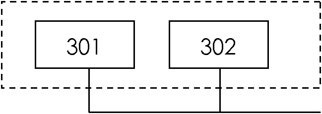

Image

  • Air conditioning system integral optimized control device
  • Air conditioning system integral optimized control device
  • Air conditioning system integral optimized control device

Examples


Embodiment Construction

[0031] The implementation of the present invention will be further described below in conjunction with the accompanying drawings, but the implementation and protection scope of the present invention are not limited thereto.

[0032] The feature of the present invention is that the control system incorporates ideas such as the physical and mathematical model of the operating characteristics of the central air-conditioning system, artificial intelligence and actual operating experience correction, and the background program of the computer workstation runs the physical and mathematical model in real time to automatically optimize to obtain different loads and different outdoor loads. The optimal operating conditions of the air-conditioning system under environmental and other conditions. According to the on-site debugging results and actual operating experience, the calculation results are revised to improve the control accuracy. Artificial intelligence plays a key role in the loa...


PUM


Abstract

The invention provides an air conditioning system integral optimized control device. The device comprises a host (101), a weak current control system (102), and a strong current control system (103), wherein both the weak current control system (102) and the strong current control system (103) are connected in parallel with the host (101) via an RS485 communication interface. The control device provided by the invention realizes the control completely compatible and parallel with an original central air conditioning control circuit, and has a local control mode and a remote control mode, wherein the local mode is applicable to site button operation, and the remote mode is applicable to remote computer remote control operation. The remote mode is divided into an automatic mode and a manualmode, wherein the manual mode can realize remote inching equipment operation, and the automatic mode can realize the full-automatic, failure-free and optimized operation of the central air conditioning system.

Description

technical field [0001] The invention relates to the technical field of central air-conditioning energy saving, in particular to an overall optimization control device for a central air-conditioning system. Background technique [0002] Large-scale central air-conditioning systems generally have more than 30% ineffective energy consumption. In actual operation, the maximum load of the air-conditioning system that operates throughout the year generally does not exceed 10% of the total operating time. Since the selection of air-conditioning equipment is based on the design conditions Definitely, and the air conditioning system works at a load rate below 80% most of the time. The energy saving of the central air-conditioning system has been paid more and more attention by people. [0003] At present, among the central air-conditioning energy-saving technologies, including water pump frequency conversion technology, chilled water system fuzzy control technology, neural network t...

Claims


Application Information

Patent Timeline
Patent Type & Authority Applications(China)
IPC IPC(8): F24F11/00
Inventor 刘雪峰刘金平邹伟刘磊文建良余荣学麦粤帮
Owner SOUTH CHINA UNIV OF TECH
Learn More