
Electromagnetic indicating device

An indicator device, electromagnetic technology, applied in the direction of electrical digital data processing, instrumentation, input/output process of data processing, etc., can solve the problem of small size

Active Publication Date: 2013-03-13
WACOM CO LTD
View PDF2 Cites 0 Cited by
  • Summary
  • Abstract
  • Description
  • Claims
  • Application Information

AI Technical Summary

Problems solved by technology

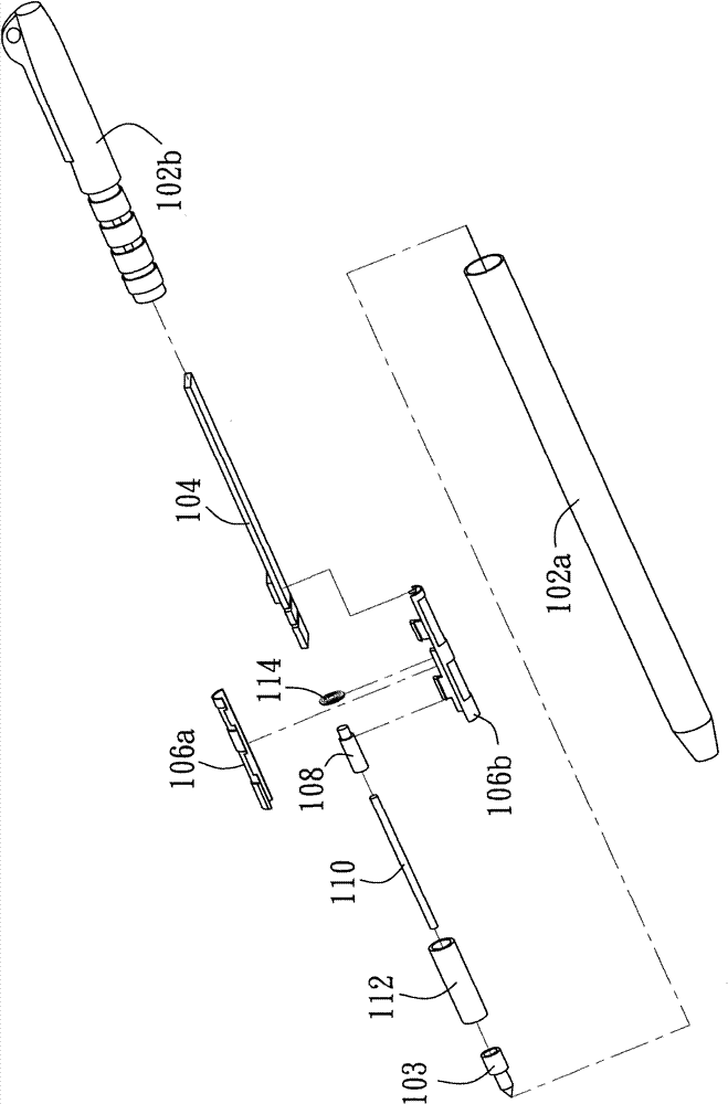
[0006] The object of the present invention is to provide an electromagnetic indicator device with a new structure. The technical problem to be solved is to make it use a metal needle as a linkage mechanism, which can trigger a switch element when writing with the refill, as a function of changing the electromagnetic pen. The signal mechanism enables the writing module to work normally, so as to overcome the shortcomings of the existing battery-free pen structure technology that cannot achieve a size smaller than 6mm in diameter

Method used


Image

  • Electromagnetic indicating device
  • Electromagnetic indicating device
  • Electromagnetic indicating device

Examples


Embodiment Construction

[0030] Some embodiments of the present invention will be described in detail as follows. However, in addition to the following description, the present invention can also be widely implemented in other embodiments, and the scope of the present invention is not limited by the embodiments, and the claims shall prevail. Furthermore, in order to provide a clearer description and easier understanding of the present invention, the various parts in the drawings are not drawn according to their relative dimensions. Some dimensions have been exaggerated compared with other related scales; the irrelevant details are not completely drawn. , In order to simplify the schema.

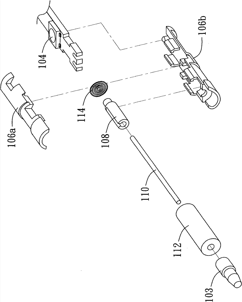
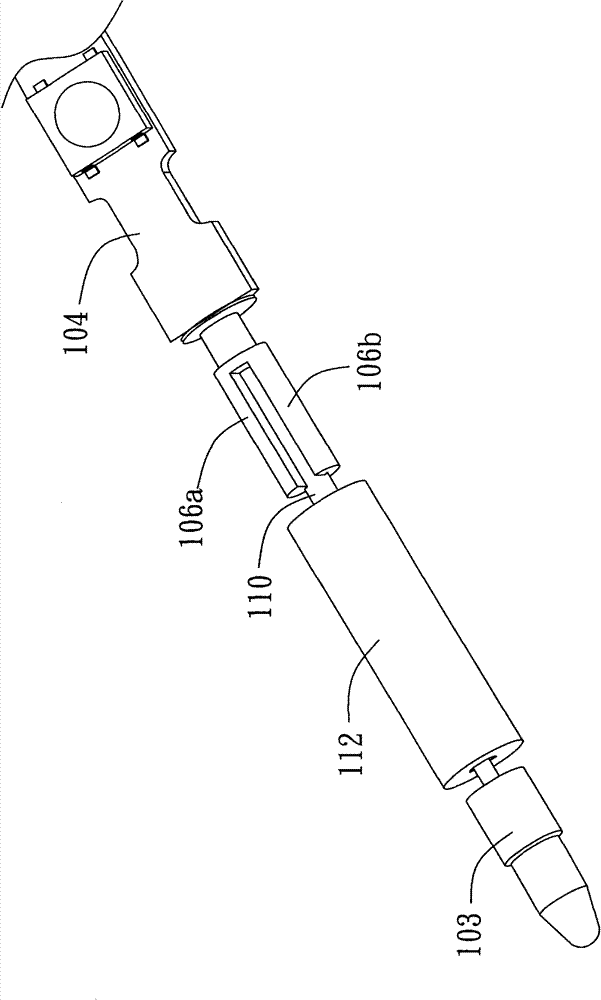
[0031] Figure 1A It is an exploded view of an electromagnetic indicator device according to an embodiment of the present invention. The electromagnetic pointing device includes pen case components 102a and 102b, pen tip component 103, a circuit board 104, a metal needle 110, a ferrite core (or called a magnetic ring) 1...


PUM


Abstract

The invention relates to an electromagnetic indicating device which comprises a pen shell component, a circuit board, a metal needle, a ferrite core and a triggering device, wherein the diameter of the pen shell component is less than 6 millimeters; the circuit board comprises a resonance circuit; the metal needle comprises a metal needle with low permeability (mu); the ferrite core and a coil which is wound on the ferrite core form an inductor and are electrically connected with the circuit board through wires to finish the resonance circuit; the center of the ferrite core is hollow; and the metal needle passes through the ferrite core and slides in the ferrite core to start the triggering device, thereby changing the electric property of the resonance circuit.

Description

Technical field [0001] The present invention relates to an electromagnetic indicator device, in particular to a battery-less electromagnetic indicator device that can be used for E-book / Green book. Background technique [0002] Input devices or electronic devices such as Digitizer tablets or E-books (E-book / Green book) have antennas or induction coils to form a sensing plane and are arranged under the working surface of the digital tablet or behind the screen of the e-book. The pointer is operated, and the coordinate position of the pointing device is obtained by the transmission and reception of electromagnetic waves between the resonance circuit in the pointing device and the antenna or induction coil. [0003] The resonant circuit of a pointing device such as an electromagnetic pen or a stylus usually includes inductors, capacitors and related components and is placed in a pen case. Inductors are mostly composed of ferrite cores (ferrite cores) wound with metal coils and capaci...

Claims


Application Information

Patent Timeline
Patent Type & Authority Patents(China)
IPC IPC(8): G06F3/0354
Inventor 连建枷刘政旅
Owner WACOM CO LTD
Learn More