Liquid cooling type radiator

A liquid cooling and radiator technology, applied in the direction of electric solid devices, semiconductor devices, semiconductor/solid device components, etc., can solve the problem that the cooling effect of the radiator cannot be uniform, the distribution of cooling liquid flow is uneven, and the cooling effect of the radiator is different. problem, to achieve the effect of small difference, equalization of flow, and improvement of uniformity

Inactive Publication Date: 2011-07-27
FUJI ELECTRIC HLDG CO LTD
View PDF5 Cites 12 Cited by
  • Summary
  • Abstract
  • Description
  • Claims
  • Application Information

AI Technical Summary

Problems solved by technology

In this way, when the flow distribution of the cooling liquid in the plurality of parallel cooling liquid circulation channels in the radiator is not uniform, the coo

Method used


Image

  • Liquid cooling type radiator
  • Liquid cooling type radiator
  • Liquid cooling type radiator

Examples


no. 1 example

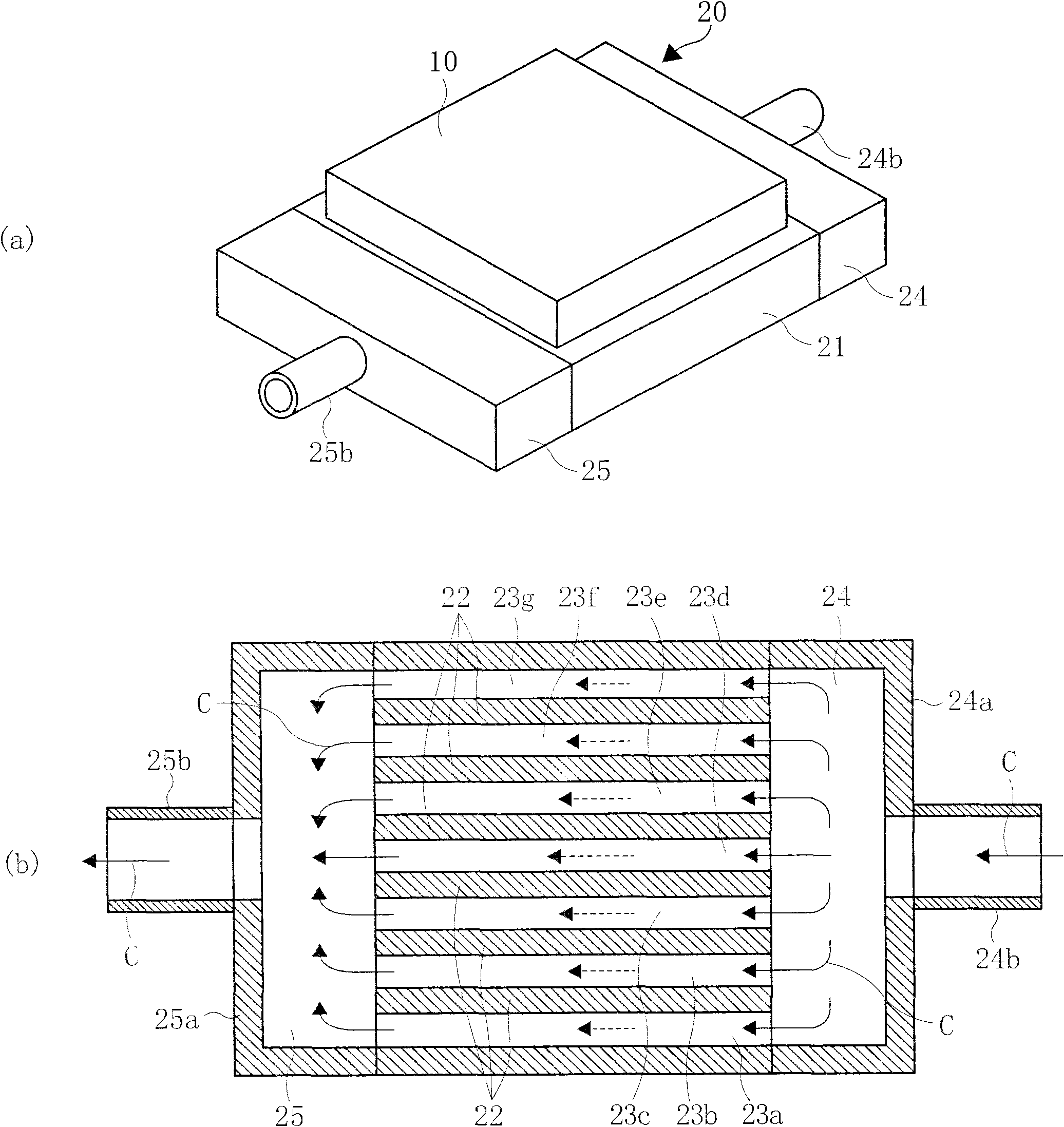
[0039] figure 1 represents the first embodiment of the present invention, figure 1 The configuration of the liquid cooling type radiator according to the first embodiment of the present invention is shown, wherein (a) is a perspective view showing the appearance, and (b) is a plan sectional view showing the internal configuration.

[0040] exist figure 1In the reference numeral 10, a modular semiconductor element as a heating element is bonded to the surface of a flat rectangular parallelepiped heat sink 20 made of a high thermal conductivity material such as copper or aluminum. The radiator 20 is provided with a radiator main body 21, and a plurality of fins 22 arranged in parallel at intervals therein form a plurality of cooling liquid flow passages 23 (23a to 23g). At both ends of the radiator main body 21 , an inflow header 24 through which the cooling liquid flows in and an outflow header 25 through which the cooling liquid flows out communicate with the cooling liqu...

no. 2 example

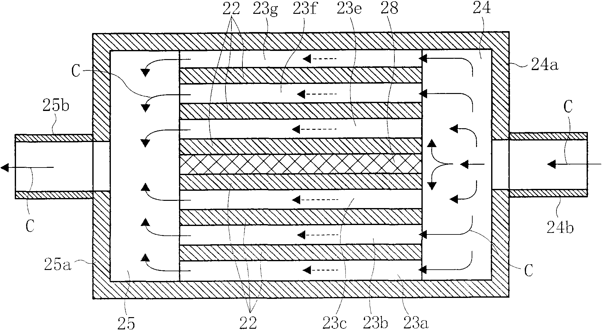
[0046] figure 2 Shows the second embodiment of the present invention. In the second embodiment, in the first embodiment, the flow rate of the cooling liquid circulation channel 23d located in the center is suppressed from being large, so that the flow rate of the cooling liquid circulating through each cooling liquid circulation channel is more equal.

[0047] The second example is figure 2 As shown, the closing body closes the cooling liquid circulation channel 23d in the center of the radiator main body 21 opposite to the cooling liquid inlet 24b and the cooling liquid outlet 25b, and serves as the cooling liquid flow control mechanism 28. Therefore, the cooling liquid from the cooling liquid inflow header 24 toward the central cooling liquid flow passage 23d is distributed and supplied to the cooling liquid flow passages on both sides, so the flow rates of the remaining cooling liquid flow passages 23a to 23c and 23e to 23g increase and the flow rates distributed as f...

no. 3 example

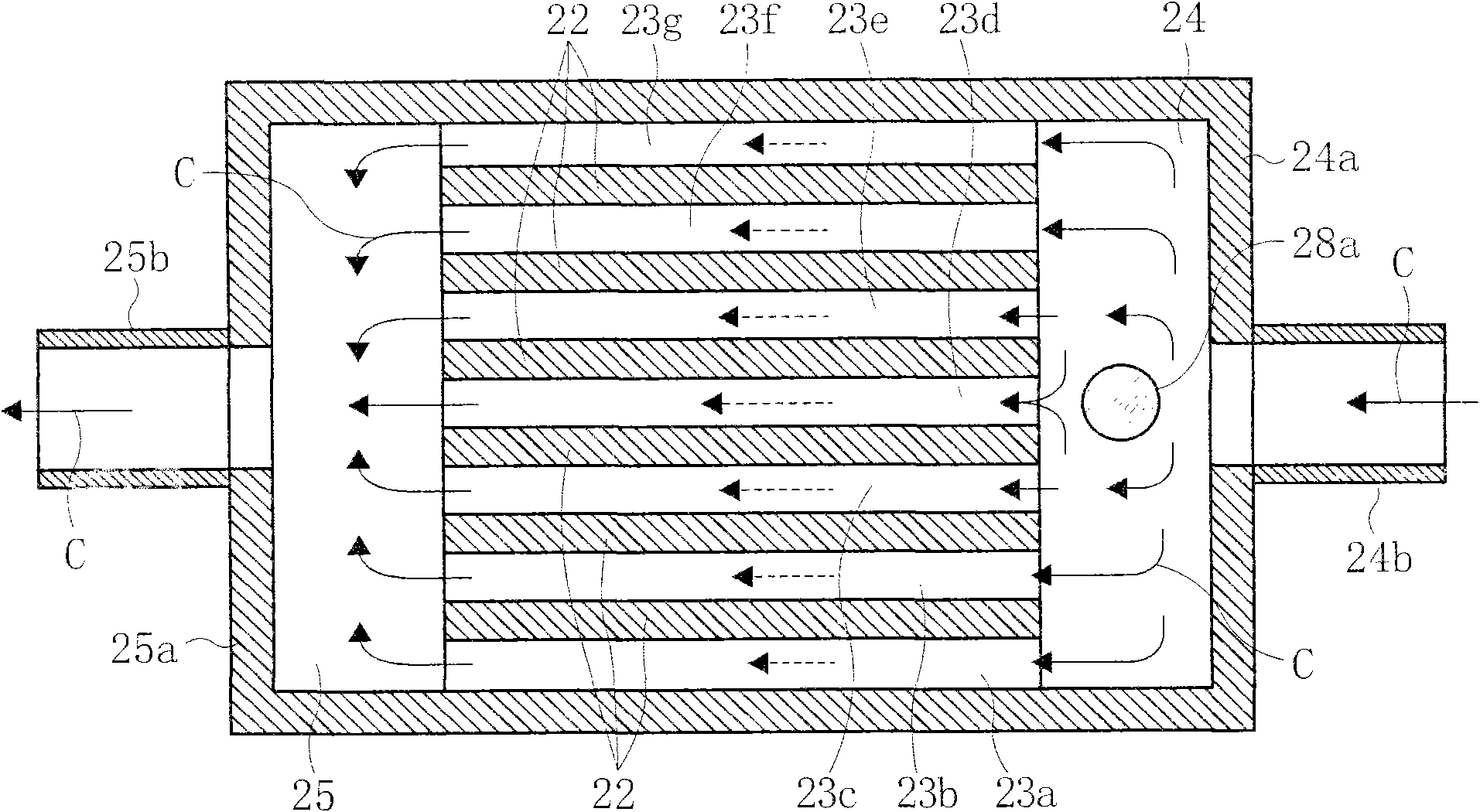
[0050] image 3 Shown is the third embodiment of the present invention.

[0051] In this third embodiment, between the cooling liquid inflow port 24b in the cooling liquid inflow header 24 and the central cooling liquid circulation channel 23d, a control protrusion 28a for guiding the cooling liquid flow from the center to both sides is provided, The inflow of the cooling liquid to the central cooling liquid circulation passage 23d is restricted.

[0052] The control protrusion 28a restricts the amount of cooling liquid flowing into the central cooling liquid flow path 23d, which usually has a large flow rate. Therefore, the flow rate of the central cooling liquid flow path 23d decreases, and the flow rates of the other cooling liquid flow paths on both sides Relatively increased, the flow distribution of the overall flow channel is as follows image 3 Homogenization is obtained as indicated by the dotted arrow. Therefore, the uniformity of the cooling effect of the entire ...


PUM


Abstract

The invention relates to a liquid cooling type radiator, which comprises a radiator main body composed of high thermal conductivity materials. The radiator main body is flat and a heating body is combined on the radiator main body. The inside of the radiator main body is provided with an inflow collector for cooling liquids to flow in, an outflow collector for cooling liquids to flow out, and a plurality of cooling liquid circulation channels formed by a plurality of radiating fins and parallel disposed with standard intervals therebetween. The inflow collector and the outflow collector are communicated and combined on the two ends of cooling liquid circulation channels formed by the radiating fins. The central part of the end face wall where the inflow collector and the outflow collector are opposed to the cooling liquid circulation channel is provided with an inflow entry and an outflow entry of the cooling liquids. A liquid cooling type radiator which enables uniform flow of cooling liquids circulating in the parallel cooling liquid circulation channels in the radiator inside and uniform cooling effects in the radiator is provided.

Description

technical field [0001] The present invention relates to a liquid cooling type heat sink used in combination with heat generating elements such as semiconductor elements for electric power. Background technique [0002] Semiconductor elements used in power conversion devices, etc., and modular semiconductor elements composed of compound semiconductor elements generate large loss heat due to increased capacity and speed. In order to improve element reliability and prolong life, it is necessary to suppress the rise in element temperature. Keep within the specified temperature. [0003] For this reason, in general, a heat generating body such as a particularly large-capacity semiconductor element or a modular semiconductor element is combined with a liquid-cooled radiator cooled by a cooling liquid such as water or salt water to cool it. [0004] Figure 6 A conventional example of a liquid cooling type radiator known from Patent Document 1 and the like is shown. In the figure...

Claims


Application Information

Patent Timeline
IPC IPC(8): H01L23/473H01L23/36
Inventor 石井美里安达昭夫
Owner FUJI ELECTRIC HLDG CO LTD
Why Eureka
Try Eureka