

Valve body assembly
A component and valve body technology, applied in the direction of lift valve, valve detail, multi-way valve, etc.
- Summary
- Abstract
- Description
- Claims
- Application Information
AI Technical Summary
Problems solved by technology
Method used
Image

Examples
Embodiment Construction
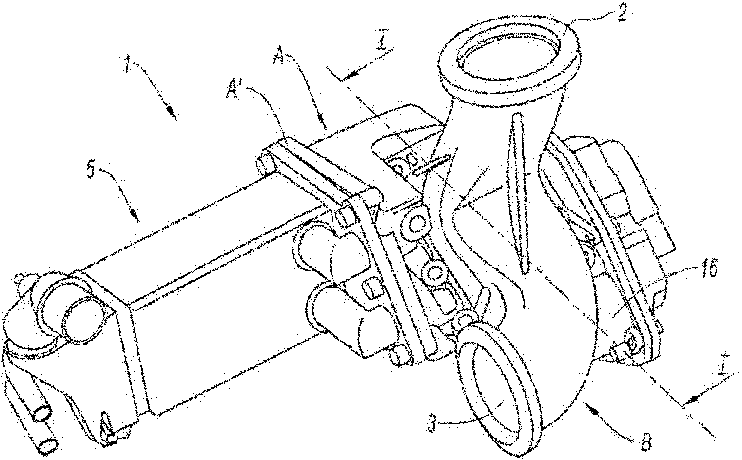
[0040] The terms front and back have been chosen in a purely conventional and arbitrary manner to simplify the description of the valves, but without prejudice to the orientation of the valves in use. In this case, front and rear are relative to the plane of the seal of the valve shutter, and rear is the end of the recirculation exhaust gas channel leading to the heat exchanger.
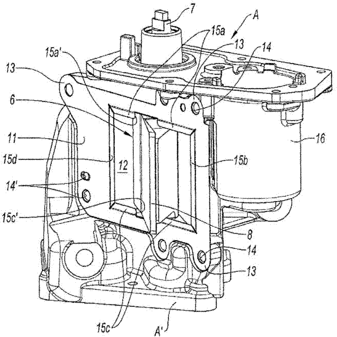
[0041] functionally, see figure 1 , a so-called "three-way" valve 1 comprising an inlet channel 2 for gas entering the valve, a first gas outlet channel 3 and a second gas outlet channel 4 . Structurally, the valve 1 comprises a valve body A, to which an exhaust pipe B is mounted and fixed;
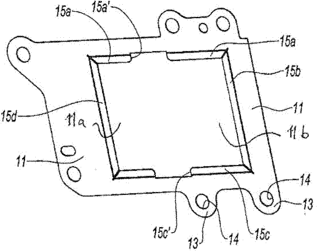
[0042] It should be noted that, by definition, a valve is a component comprising a valve shutter and a plurality of channels, while the valve body is a structural element of the valve supporting the valve shutter 6 .
[0043] The first outlet channel 3 is a direct exhaust gas outlet channel; it is called exhau...
PUM
 Abstract
Description
Claims
Application Information