Valve body assembly

A component and valve body technology, applied in the direction of lift valve, valve detail, multi-way valve, etc.

Inactive Publication Date: 2013-10-30
VALEO SYST DE CONTROLE MOTEUR
View PDF4 Cites 0 Cited by
  • Summary
  • Abstract
  • Description
  • Claims
  • Application Information

AI Technical Summary

Problems solved by technology

The applicant does not however intend to limit the scope of its claims to this application only, but aims to solve the more general problem of sealing valve shutters in valve bodies including channel to tube
Even more generally, the applicant intends to solve the problem of a valve shutter sealing a valve body intended to be connected to a pipe

Method used


Image

  • Valve body assembly
  • Valve body assembly
  • Valve body assembly

Examples


Embodiment Construction

[0040] The terms front and back have been chosen in a purely conventional and arbitrary manner to simplify the description of the valves, but without prejudice to the orientation of the valves in use. In this case, front and rear are relative to the plane of the seal of the valve shutter, and rear is the end of the recirculation exhaust gas channel leading to the heat exchanger.

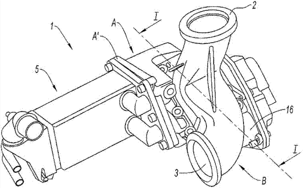
[0041] functionally, see figure 1 , a so-called "three-way" valve 1 comprising an inlet channel 2 for gas entering the valve, a first gas outlet channel 3 and a second gas outlet channel 4 . Structurally, the valve 1 comprises a valve body A, to which an exhaust pipe B is mounted and fixed;

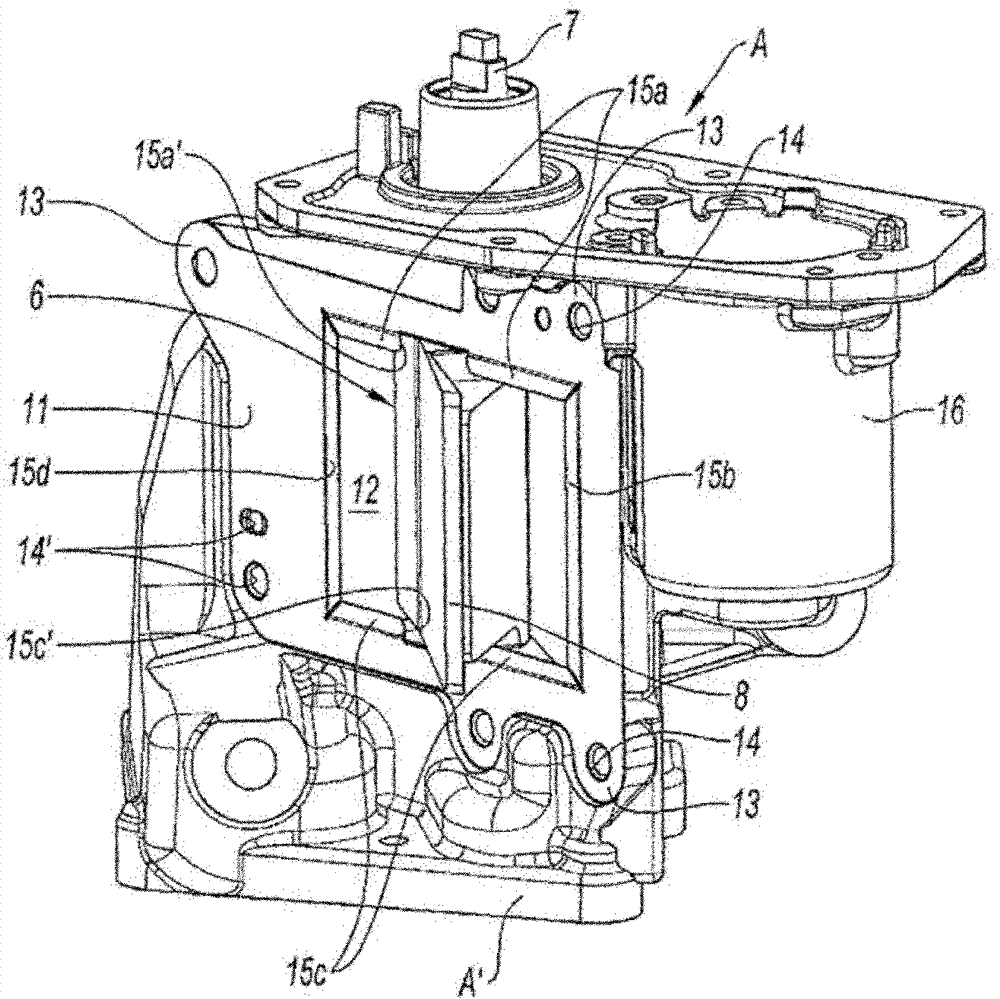
[0042] It should be noted that, by definition, a valve is a component comprising a valve shutter and a plurality of channels, while the valve body is a structural element of the valve supporting the valve shutter 6 .

[0043] The first outlet channel 3 is a direct exhaust gas outlet channel; it is called exhau...


PUM


Abstract

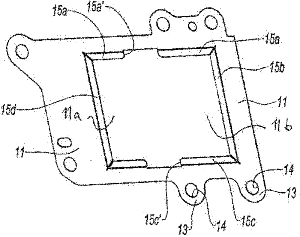
The invention concerns an assembly of a valve body (A) and a seal (11). The valve body (A) includes a gas flow passage (4) and a valve shutter (6) mobile between an open position and a closed position obstructing the movement of the gases in the passage (4). The passage (4) being intended to be connected to a pipe (B) to enable gas to flow between them, the seal (11) being intended to be mounted between the passage (4) and the pipe (B) to provide a gas seal between them. The assembly is characterized in that the seal (11) forms a seat for the valve shutter (6) in the closed position. The seal provides, on the one hand, a seal between the passage and the pipe whether the valve shutter is in the open or the closed position and, on the other hand, a seal for the valve shutter in the closed position.

Description

technical field [0001] The invention relates to valve body and seal assemblies. Background technique [0002] A motor vehicle internal combustion engine includes a combustion chamber, typically a plurality of cylinders, in which a mixture of fuel and a combustive agent is combusted to produce engine work. The combustion-supporting agent is air, which is compressed or not depending on whether the engine includes a turbocharger. Air can also be mixed with the exhaust gas; this is known as exhaust gas recirculation. The gas that enters the combustion chamber is called the intake air. [0003] In the case of an engine with a turbocharger, air enters the engine, is compressed by the compressor, enters the cylinders where it is combusted with fuel, and then exits through the exhaust pipe. The exhaust gases drive a turbine that is fixed to the compressor and forms a turbocharger with it. When the exhaust gas is sucked in after the turbine and reintroduced before the compressor,...

Claims


Application Information

Patent Timeline
Patent Type & Authority Patents(China)
IPC IPC(8): F16K1/226
CPCY02T10/121F02M25/0793F16K1/2263F02M25/0796F02M25/0719F16K11/0525F02M26/16F02M26/70F02M26/71Y02T10/12F16K1/226F16K25/02
Inventor 奥德·费斯托塞巴斯蒂安·阿德诺特巴斯琴·雷赫克
Owner VALEO SYST DE CONTROLE MOTEUR
Why Eureka
Try Eureka