Window-type air conditioner

An air conditioner and window-type technology, which is applied in the field of window-type air conditioners, can solve the problems of the lower centrifugal fan falling off, interference fit loosening, fan damage, etc., and achieve the effect of preventing displacement, ensuring accuracy, and facilitating detachment

Inactive Publication Date: 2011-08-03
LG ELECTRONICS (TIANJIN) APPLIANCES CO LTD
View PDF6 Cites 3 Cited by
  • Summary
  • Abstract
  • Description
  • Claims
  • Application Information

AI Technical Summary

Problems solved by technology

[0009] In the above-mentioned integrated window-type air conditioner of the prior art, the outdoor fan adopts a centrifugal fan arranged symmetrically up and down. When the air conditioner is in cooling operation, the centrifugal fan rotates, and the air flows toward the installation direction of the condenser under the guidance and restriction of the volute. , and the heat exchange between the air and the condenser takes away the heat on the condenser continuously, thereby completing the heat exchange outside the window air conditioner, so that the cooling work of the air conditioner can be carried out continuously. In the existing structure, the lower motor shaft and the lower centrifugal The fans are connected through the interference fit between the lower motor shaft and the inner wall of the lower fan shaft. During the long-term operation of the air conditioner, the interference fit is prone to loosening, and because the lower centrifugal fan itself has a certain mass, it will The gravity of the middle and lower centrifugal fan is perpendicular to the friction force of the interference fit. The lower centrifugal fan itself has a downward movement tendency. The lower centrifugal fan is easy to fall off the lower motor shaft, which will cause damage to the fan or affect the normal operation of the air conditioner.

Method used


Image

  • Window-type air conditioner
  • Window-type air conditioner
  • Window-type air conditioner

Examples


Embodiment Construction

[0033] The present invention will be described in detail below with reference to the drawings and examples.

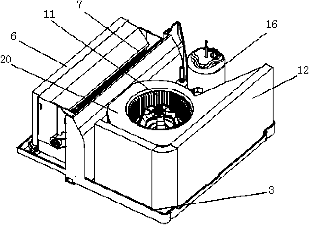
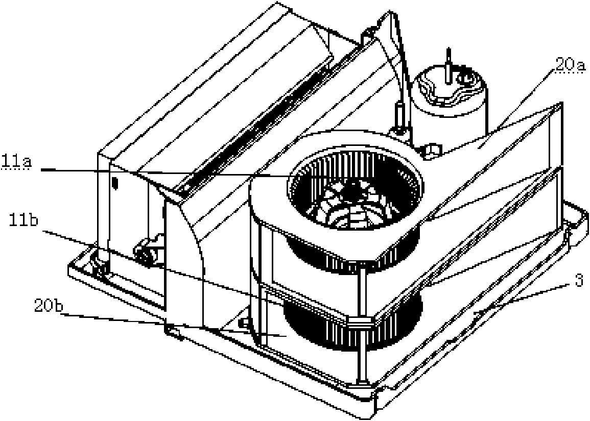
[0034] Figure 4 It is a structural schematic diagram of the outdoor part of the window air conditioner of the present invention; Figure 5 It is a partially enlarged view of the outdoor fan part in the window air conditioner of the present invention.

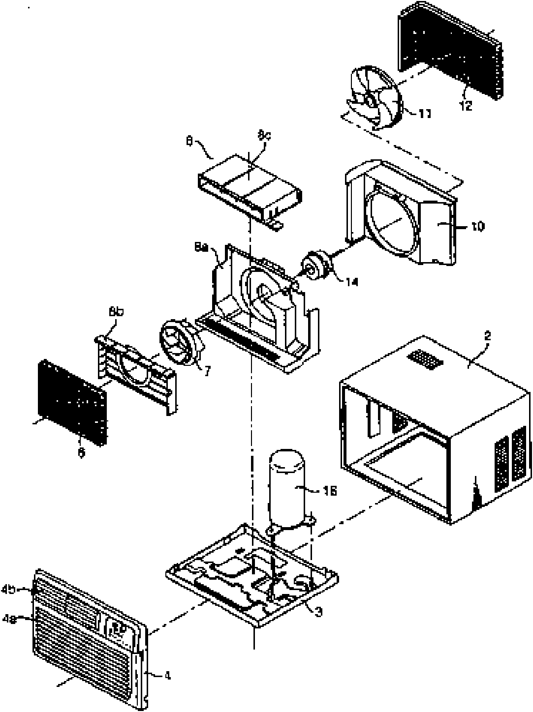
[0035] Such as Figure 4 , Figure 5As shown, in the window air conditioner of the present invention, the indoor panel is arranged on the front end of the air conditioner facing the indoor side, and an air inlet, an exhaust port and a control part are formed, and the air conditioner sucks in air from the air inlet during operation , and then the heat-exchanged air is discharged into the room again through the exhaust port to complete the temperature adjustment; the casing forms the appearance of the air conditioner and accommodates various components of the air conditioner. The above-mentioned casing is formed on the...


PUM


Abstract

The invention discloses a window-type air conditioner, which comprises an indoor panel, a case, an evaporator, an indoor fan, a condenser, an outdoor fan, a motor, a compressor and a base plate, wherein an elastic bump is arranged at the tail end of a lower motor shaft; and a groove matched with the elastic bump is formed on the inner wall of a lower fan shaft which is combined with a lower centrifugal fan and the lower motor shaft. When the lower motor shaft and the lower centrifugal fan are arranged, the elastic bump is used for clamping the groove in the lower fan shaft and fixing the lower centrifugal fan and the lower motor shaft, so that the lower centrifugal fan is firmly fixed with the lower motor shaft together; the elastic bump is arranged on a flat part at the tail end of the lower motor shaft, so that the transmission of power to the lower centrifugal fan through the lower motor shaft can be ensured, and the accuracy of a fixed position can be ensured; and when the centrifugal fan is required to be detached, only a button on the lower motor shaft is required to be pushed, so that the elastic bump is retracted towards the inside of the lower motor shaft, namely the elastic bump can be separated from the groove, and the lower centrifugal fan can be conveniently separated from the lower motor shaft.

Description

technical field [0001] The present invention relates to the technical field of window-type air conditioners, specifically, a movable elastic protrusion is arranged at the end of the lower motor shaft, and the elastic protrusion cooperates with a groove provided on the inner wall of the lower fan shaft, so that the lower centrifugal fan can be connected to the lower fan shaft. Window type air conditioner that the motor shaft is firmly fixed and easy to disassemble. Background technique [0002] Generally, an air conditioner is a device that cools or heats an indoor environment to create a comfortable indoor environment, and is roughly classified into an integrated type air conditioner and a split type air conditioner. [0003] Although the functions of the integrated air conditioner and the split air conditioner are the same, the integrated air conditioner is equipped with cooling and heat dissipation components in the same casing, and is installed on the wall or on the windo...

Claims


Application Information

Patent Timeline
Patent Type & Authority Applications(China)
IPC IPC(8): F24F1/02
Inventor 李占高建忠王柳
Owner LG ELECTRONICS (TIANJIN) APPLIANCES CO LTD
Why Eureka
Try Eureka