Resistance-type concrete abrasion sensor and measurement method thereof
A concrete and resistive technology, applied in the field of sensors, can solve problems such as insufficient measurement accuracy, insufficient measurement range, and limited number of cable core wires, and achieve the effect of simple working principle, simple measurement method, and reduced monitoring costs
- Summary
- Abstract
- Description
- Claims
- Application Information
AI Technical Summary
Problems solved by technology
Method used
Image

Examples
Embodiment approach 1
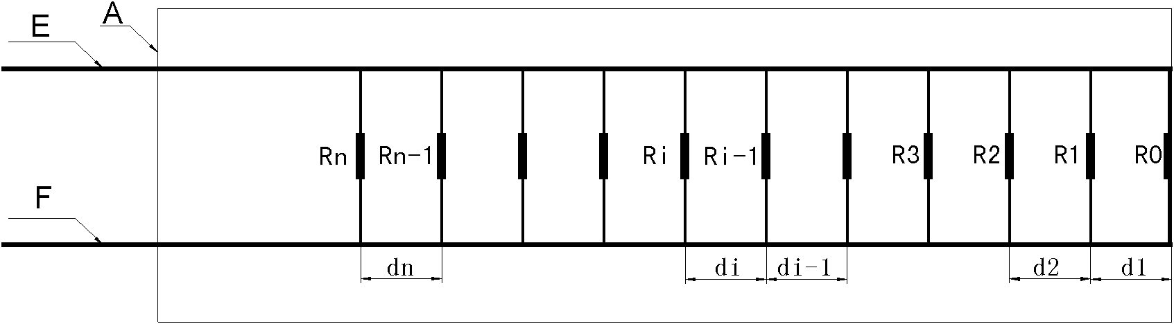
[0039] Such as Figure 4 Shown, the resistive concrete abrasion sensor consists of:
[0040] (1) A sensor body A made of an insulating material, and the abrasion resistance of the body A is close to but not higher than that of the concrete material;
[0041] (2) Wire E and wire F, and perpendicular to the end face of the sensor body;
[0042] (3) Eleven lead wires parallel to the end face of the sensor body, the distance between each lead wire is 10mm, and the first lead wire at the end face of the sensor body is directly connected;
[0043] (4) According to the order of the leads, the fixed resistance values connected in series in the leads are as follows: R0=0Ω, R1=100Ω, R2=300Ω, R3=510Ω, R4=510Ω, R5=1kΩ, R6=1kΩ, R7=1kΩ, R8 =1.5kΩ, R9=1.5kΩ, R10=1.5kΩ.
[0044] The specific steps of the resistive concrete abrasion sensor measurement method are:
[0045] (1) Firstly, according to the fixed resistance value in the sensor body, calculate the parallel resistance value Rbi ...
Embodiment approach 2
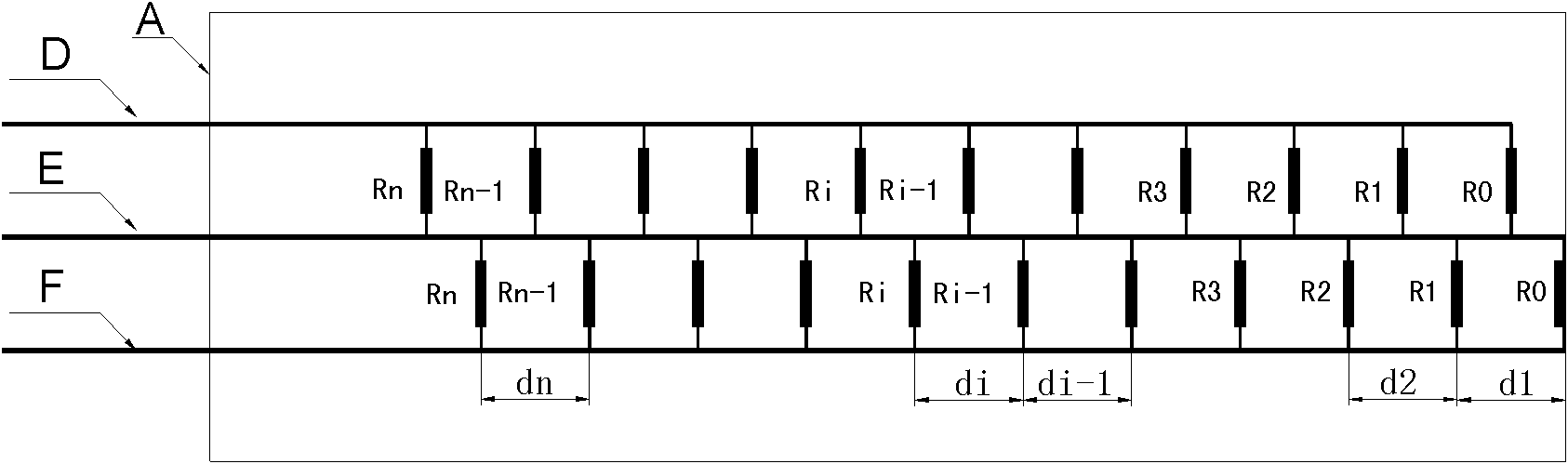
[0053] Such as Figure 5 As shown, the working principle of embodiment 2 is the same as that of embodiment 1, including:
[0054] (1) A sensor body A made of an insulating material, and the abrasion resistance of the body A is close to but not higher than that of the concrete material;
[0055] (2) Conductor D, conductor E and conductor F, and perpendicular to the end face of the sensor body;
[0056] (3) Two sets of lead wires, each group is eleven, respectively connected to wire E and wire F and wire E and wire D, and the lead wires are parallel to the end surface of the sensor body;
[0057](4) The first lead wires of wire E and wire F are at the end face of the sensor body, and the first lead wires of wire E and wire D are 5mm away from the end face of the sensor body; in the same lead wire group, the distance between the lead wires is 10mm;
[0058] (5) According to the order of the lead wires, the fixed resistance values connected in series in the lead wires are as f...
Embodiment approach 3
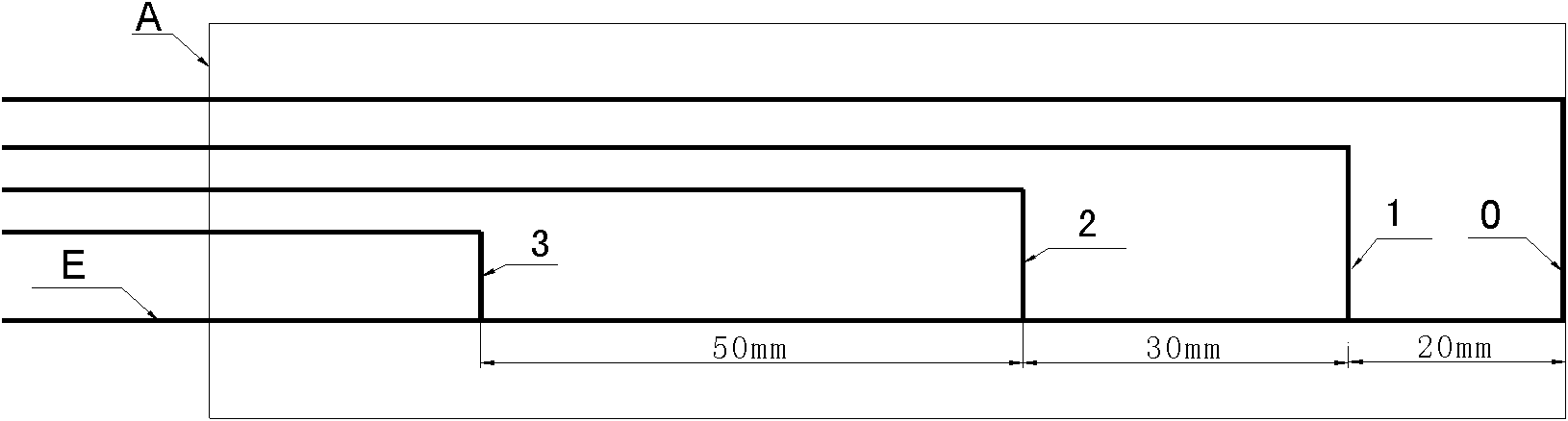
[0069] Such as Figure 6 As shown, Embodiment 3 is basically the same as Embodiment 1. In this solution, three calibration lines are added to the sensor body A; the distances between the three calibration lines and the end face of the sensor body are 20mm, 50mm, and 100mm respectively, which are in line with the concrete abrasion damage standard (mild, moderate, severe). The calibration line checks the abrasion depth of concrete and also plays a backup role.
PUM
 Abstract
Description
Claims
Application Information
 - Generate Ideas
- Intellectual Property
- Life Sciences
- Materials
- Tech Scout
- Unparalleled Data Quality
- Higher Quality Content
- 60% Fewer Hallucinations
Browse by: Latest US Patents, China's latest patents, Technical Efficacy Thesaurus, Application Domain, Technology Topic, Popular Technical Reports.
© 2025 PatSnap. All rights reserved.Legal|Privacy policy|Modern Slavery Act Transparency Statement|Sitemap|About US| Contact US: help@patsnap.com