Liquid-gas coupling differential pressure type bridge deflection test method

A technology of bridge deflection and testing method, applied in pressure difference measurement between multiple valves, elasticity testing, and testing of machine/structural components, etc., can solve problems such as poor operability, low work efficiency, and large errors

Active Publication Date: 2009-06-10
CHINA RAILWAY BRIDGE SCI RES INST LTD +1
View PDF5 Cites 12 Cited by
  • Summary
  • Abstract
  • Description
  • Claims
  • Application Information

AI Technical Summary

Problems solved by technology

In the current bridge inspection and health monitoring process, the bridge deflection test generally adopts the following methods: 1. Use optical measuring instruments such as level gauges to measure bridge deflection. Although the operation is simple, the measurement accuracy is low, especially when bridge inspections are often carried out at night. The measurement results are greatly disturbed by human influence, and the error is relatively large. Moreover, when the longitudinal slope of the bridge is large, the operation needs to be turned, and the work efficiency is very low.
2. The deflection of the bridge is tested with displacement meters such as dial gauges and dial gauges. Although the accuracy is high, the installation of the fixed base is inconvenient, and data collection is difficult, and the work efficiency is slightly low.
3. Using the photoelectric image principle, the deflection value of the bridge is obtained through the collected image signal and the data processing method, such as the patent number ZL200610095083.2, the authorized announcement number CN100395515C, and the name "tension line video deflection measuring device and method" ", as well as an invention patent application with application number 200710103777.0, publication number CN101055218, and titled "Bridge Deflection and Displacement Monitoring Device and Monitoring Method". Restricted conditions, difficult data processing, and high cost, especially when testing at night, the actual operability is poor
4. Based on the principle of the connecting device, the deflection of the bridge is directly measured according to the change of the liquid level in the open connecting pipe. When the longitudinal slope of the bridge is large, a connecting pipe is usually connected between every two measuring points. The principle of this method is simple , but the actual test results show that due to the viscous resistance between the liquid and the pipe wall and the capillary action between the water and the pipe wall, the test accuracy is not high, and there is a large error in the zero reading after unloading. Due to the surface tension of the liquid, the liquid surface is non-horizontal, and there are large errors in the readings
5. Based on the principle of the connector, directly convert the deflection into the pressure of the liquid in the pipe, and use a pressure transmitter to convert the pressure change into a change in deflection. For example, the patent number is 200310108447.2, the authorized announcement number is CN100385201C, and the name is "Large-span Bridge Deflection monitoring method" is an invention patent, the method is theoretically feasible, but in the actual operation process, especially when the bridge span is large or there are many measuring points, due to the relative flow between the liquid in the pipe and the pipe wall, viscous resistance will be generated. There will be a certain degree of loss in the pressure of the liquid, resulting in a certain error in the measurement accuracy, and it only has a certain practical value in long-term bridge monitoring, and its cost is high in the bridge inspection process. However, it is difficult to install the device on site
Therefore, the existing bridge deflection test device has the following defects: 1. The test accuracy is low, the error is large, and the force characteristics of the bridge structure cannot be truly judged; 2. The test device is complicated to install, difficult to collect data, and low in efficiency; 3. The mechanism is complex, the calculation of early data is difficult, and the calculation cost and economic cost are high
4. It cannot be applied to the monitoring of bridge deflection such as large bridges and extra large bridges

Method used


Image

  • Liquid-gas coupling differential pressure type bridge deflection test method
  • Liquid-gas coupling differential pressure type bridge deflection test method
  • Liquid-gas coupling differential pressure type bridge deflection test method

Examples


Embodiment Construction

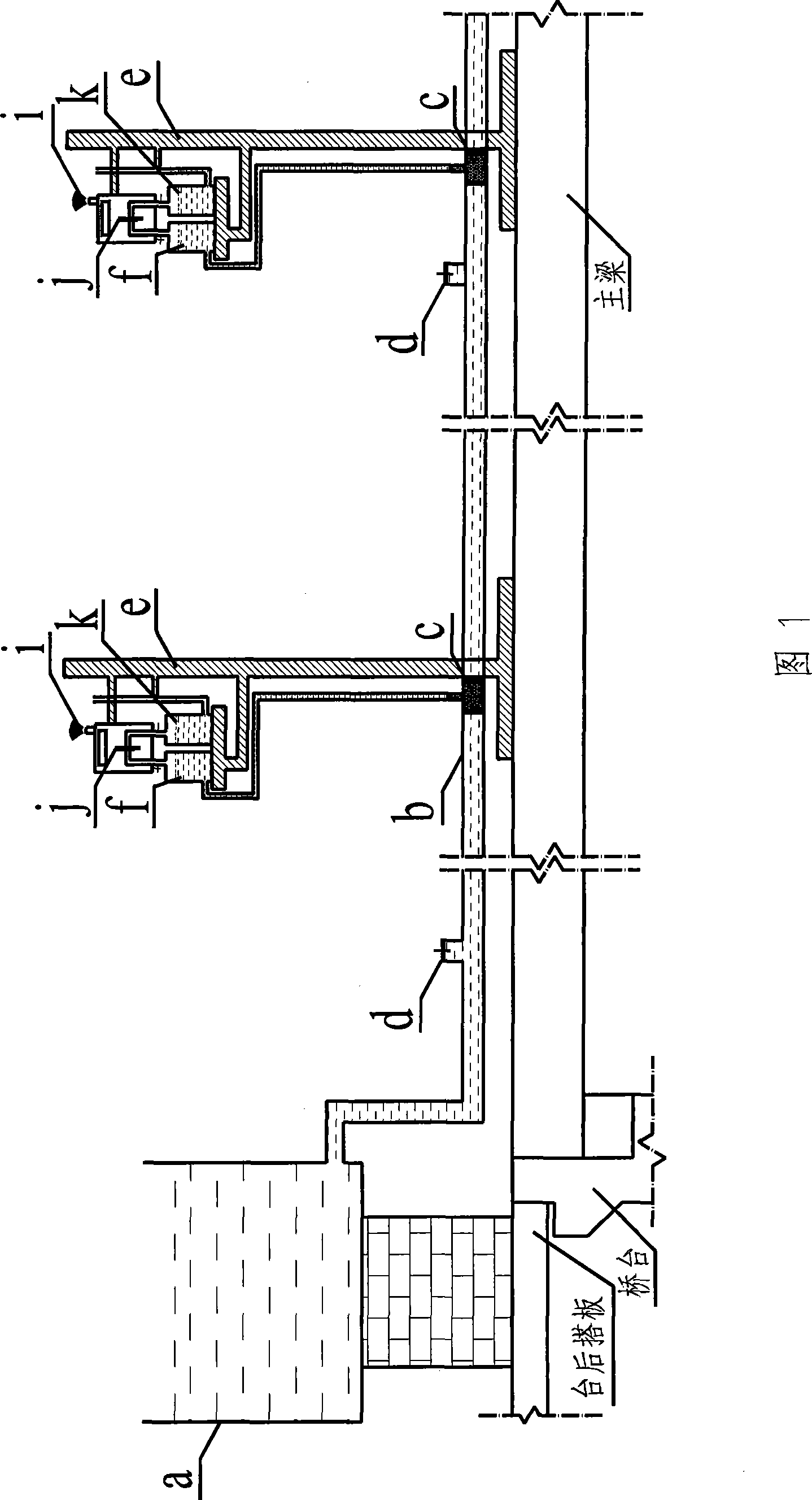
[0036] The present invention will be further described below in conjunction with the embodiments and accompanying drawings. In this embodiment, the range of the pressure difference sensor j is -2000Pa~2000Pa, and the pressure test accuracy can be selected as 1.0Pa to meet the actual test requirements, and the corresponding displacement test accuracy is 0.1 mm.

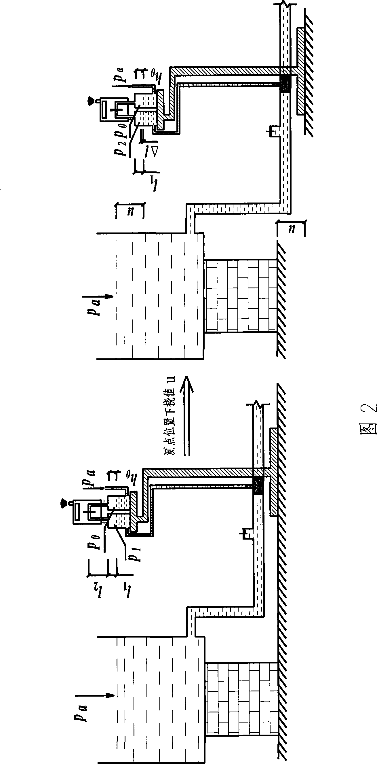
[0037] Fig. 1 is a schematic structural diagram of the bridge deflection testing method of the present invention, and Fig. 2 is a schematic structural structural diagram of the bridge deflection testing method of the present invention. Due to the sealing of a small section of gas at the end of the connecting pipe b, as well as the regulating effect of the gas column regulator f and the liquid regulating box a, the liquid in the connecting pipe b will be in a quasi-quiescent state during the whole test process. The liquid in the connecting pipe b can be water. When the temperature is low, an appropriate amount of antifr...


PUM

PropertyMeasurementUnit
diameteraaaaaaaaaa
diameteraaaaaaaaaa

Abstract

The invention provides a liquid-gas coupling pressure difference type bridge deflection test method, which overcomes the defect of the prior open communicating pipe deflection test method, and converts change of liquid-gas coupling pressure difference in the whole test into change of bridge deflection, namely, gas with smaller volume is sealed at each test point end, meanwhile, because assistant actions of each gas column adjuster and a liquid adjusting box, liquid in a communicating pipe is in a quasi stationary state during whole test. The method effectively overcomes viscous damping force and capillary effect generated due to relative flow between a pipe wall and the liquid, in addition, the method transmits pressure reading of an air pressure difference sensor to a signal acquisition system conveniently in time through a signal transmitting device, so as to calculate a deflection value of each test point. Therefore, the method not only has high measuring accuracy, but also has high measuring efficiency and higher utility value.

Description

technical field [0001] The invention relates to a bridge deflection test method, which is applicable to the deflection test of multiple control measuring points of any bridge span length, belongs to the technical field of bridge detection and monitoring, and specifically relates to a bridge detection and health monitoring process. High-precision and high-efficiency bridge deflection testing method. technical background [0002] In the process of bridge inspection and health monitoring, the bridge will produce a certain amount of deflection and deformation under the action of live loads such as automobiles. The deformation of the damaged bridge structure is even in a nonlinear state, and a certain residual deformation will occur after the live load is removed. Therefore, as an important evaluation parameter, the deflection of the bridge has important theoretical value for testing and evaluating the real mechanical characteristics of the bridge structure; Timeliness requireme...

Claims


Application Information

Patent Timeline
Patent Type & Authority Applications(China)
IPC IPC(8): G01M5/00G01B13/24G01L13/00
Inventor 汪正兴王波周明星朱世峰钟继卫张建平胡贵琼付文胜叶觉明
Owner CHINA RAILWAY BRIDGE SCI RES INST LTD
Why Eureka
Try Eureka