Hydraulic system of hydraulic damper test bench

A hydraulic damper and hydraulic system technology, which is applied in the field of hydraulic systems, can solve problems affecting product testing accuracy, achieve the effects of improving product testing accuracy, achieving reliable pressure maintenance, and ensuring locking requirements

Inactive Publication Date: 2011-08-03
常州格林电力机械制造有限公司
View PDF5 Cites 21 Cited by
  • Summary
  • Abstract
  • Description
  • Claims
  • Application Information

AI Technical Summary

Problems solved by technology

The usual hydraulic damper test bench has only one set of test cylinders. Since there are many specifications and models of pipeline hydraulic dampers, only one set of test cylinders will affect the test accuracy of the product.

Method used


Image

  • Hydraulic system of hydraulic damper test bench
  • Hydraulic system of hydraulic damper test bench
  • Hydraulic system of hydraulic damper test bench

Examples


Embodiment Construction

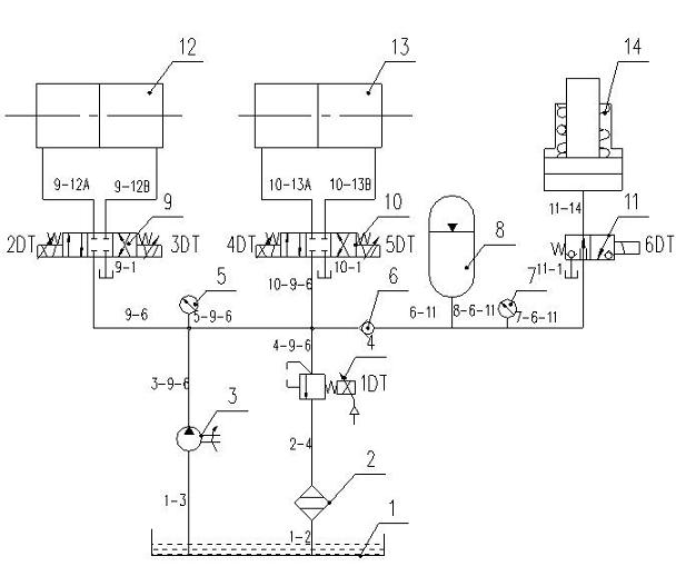
[0022] Such as figure 1 As shown, a hydraulic system of a hydraulic damper test bench includes a fuel tank 1, an oil return filter 2, an oil pump 3, a proportional overflow valve 4, a system pressure gauge 5, a check valve 6, a remote pressure gauge 7, and an energy storage Device 8, proportional reversing valve 9, proportional reversing valve 10, electromagnetic ball valve 11, small-level test cylinder 12, large-level test cylinder 13, locking cylinder 14 and related connecting pipes and passages.

[0023] The inlet of oil pump 3 is connected to pipeline 1-3, and oil is sucked from oil tank 1 through pipeline 1-3, the outlet of oil pump 3 is connected to pipeline 3-9-6, and high-pressure oil is supplied to the system through pipeline 3-9-6 .

[0024] The inlet of proportional overflow valve 4 is connected to pipeline 4-9-6, and the outlet is connected to oil return filter 2 through pipeline 2-4. Proportional overflow valve 4 is equipped with proportional electromagnet 1DT, w...


PUM


Abstract

The invention discloses a hydraulic system of a hydraulic damper test bench, comprising the hydraulic damper test bench and a hydraulic control system. The hydraulic control system comprises a large-level test oil cylinder and a small-level test oil cylinder which are arranged on the hydraulic damper test bench, a central frame is arranged on the hydraulic damper test bench between the large-level test oil cylinder and the small-level test oil cylinder, and a large-level hydraulic damper and a small-level hydraulic damper can be respectively clamped between the central frame and the large-level test oil cylinder as well as between the central frame and the small-level test oil cylinder. In the invention, the test requirements of the large-level hydraulic damper product and the small-level hydraulic damper product are satisfied respectively with the utilization of the large test oil cylinder and the small test oil cylinder, thereby the test accuracy of the product is enhanced; the tensile and compress test requirements and the speed requirements of the hydraulic dampers are satisfied with the utilization of a proportional reversing valve; the test loading requirements in different specifications of the hydraulic dampers are satisfied with the utilization of a proportional relieve valve; and with the utilization of a locking oil cylinder and a pressure keeping loop, reliable locking of the center frame of the test bench is ensured, and continuous working of the hydraulic damper test bench can be also ensured.

Description

technical field [0001] The invention relates to a hydraulic system, in particular to a hydraulic system used for a hydraulic damper test bench, which meets the performance test requirements of the hydraulic damper. Background technique [0002] The hydraulic damper is a device used for shock resistance and shock absorption. According to different occasions, the performance requirements of the hydraulic damper are also different. The pipeline hydraulic damper is a common hydraulic damper, one end is installed on the pipeline, the other end is installed on the fixed body, and the two ends can produce relative movement. There are two main requirements for its performance: 1. Low-speed stroke resistance; 2. Locking speed. When the pipeline is affected by thermal deformation and the radial movement speed is low, the movable part of the pipeline hydraulic damper moves with the pipeline at a low speed. At this time, the additional force generated by the pipeline hydraulic damper o...

Claims


Application Information

Patent Timeline
Patent Type & Authority Applications(China)
IPC IPC(8): G01M13/00F15B15/26F15B11/02
Inventor 钱雪松汤炳新
Owner 常州格林电力机械制造有限公司
Why Eureka
Try Eureka