Method for determining signal-to-noise ratio of optical remote sensor by combining satellite orbit characteristics

A technology for optical remote sensors and satellite orbits, which is applied in the field of aerospace optical remote sensing, and can solve problems that have not yet been raised

Inactive Publication Date: 2011-08-03
BEIJING RES INST OF SPATIAL MECHANICAL & ELECTRICAL TECH
View PDF4 Cites 16 Cited by
  • Summary
  • Abstract
  • Description
  • Claims
  • Application Information

AI Technical Summary

Problems solved by technology

Both of the above two public papers have established a mathematical model from the target to the remote sensor,

Method used


Image

  • Method for determining signal-to-noise ratio of optical remote sensor by combining satellite orbit characteristics
  • Method for determining signal-to-noise ratio of optical remote sensor by combining satellite orbit characteristics
  • Method for determining signal-to-noise ratio of optical remote sensor by combining satellite orbit characteristics

Examples


Embodiment Construction

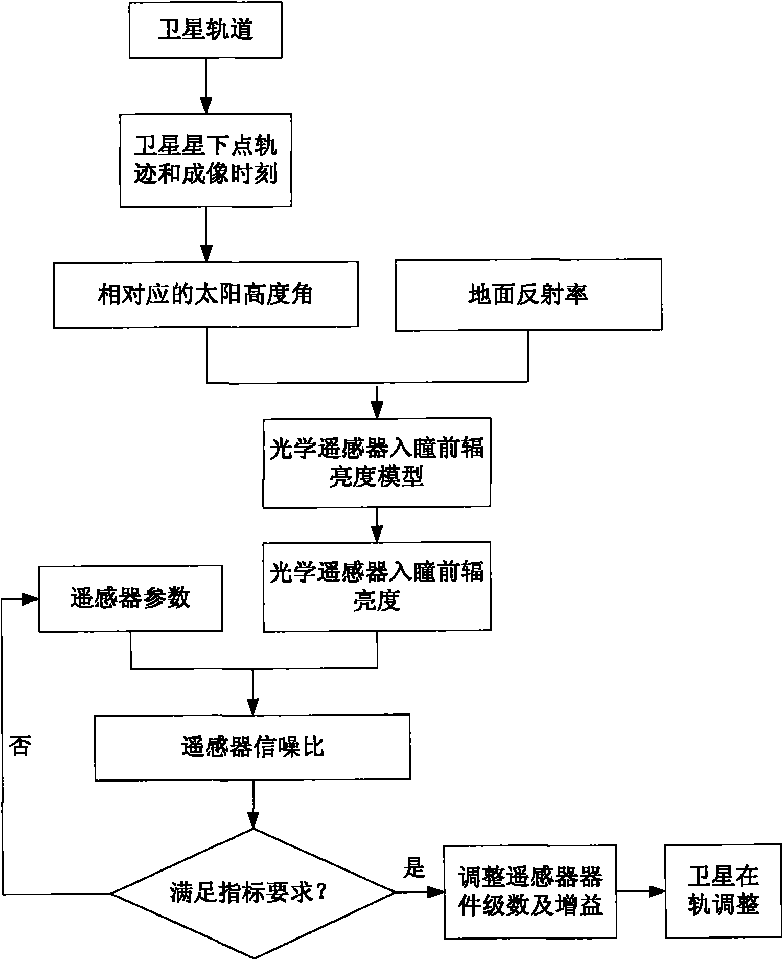
[0051] Such as figure 1 Shown, the realization process of the present invention is:

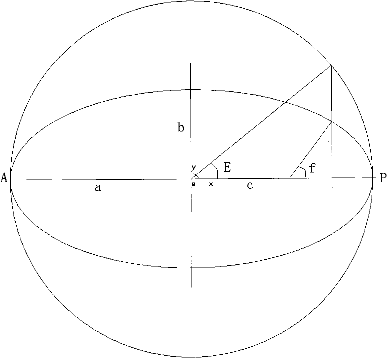
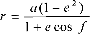
[0052] (1) The satellite moves along the conic curve, the focus F of the conic curve is located at the center of the earth, then the orbital equation of the satellite is written as the earth center distance r as:

[0053] r = a ( 1 - e 2 ) 1 + e cos f

[0054] The relationship between satellite anomaly E and true anomaly f is:

[0055] acosE=ae+rcosf

[0056] bsinE=rsinf

[0057] Derived to get:

[0058] cos E = e - cos f 1 + e cos f ...


PUM


Abstract

The invention discloses a method for determining the signal-to-noise ratio of an optical remote sensor by combining satellite orbit characteristics. During determination of the signal-to-noise ratio of the optical remote sensor, the characteristics of the flight orbit of a satellite and a ground object are taken into full consideration, and the capability of the optical remote sensor is developed to the greatest extent, so that the optical remote sensor can acquire enough energy during flight of the satellite on orbit, the imaging quality of a remote sensing satellite is greatly improved, and the problem of dark images acquired by a high-resolution on-orbit remote sensor is solved.

Description

technical field [0001] The invention relates to a method for determining the signal-to-noise ratio of an optical remote sensor combined with the characteristics of satellite orbits, in particular to a method for determining the signal-to-noise ratio of space optical remote sensors combined with the characteristics of satellite orbits, and belongs to the technical field of aerospace optical remote sensing. Background technique [0002] With the urgent need for high-resolution satellites, space optical remote sensors continue to develop. The signal-to-noise ratio is one of the important indicators for the design of space optical cameras. It is used to characterize the radiation performance of the camera and evaluate the image quality of the camera. Scientifically and rationally designing the signal-to-noise ratio of the remote sensor has become the core task in the early stage of remote sensor development, and is the key to ensure the final high image quality in orbit. The cur...

Claims


Application Information

Patent Timeline
IPC IPC(8): G01S7/497G01S17/89
Inventor 满益云阮宁娟苏云钟晓明赵海博许春晓王殿中鲍云飞张智李妥妥
Owner BEIJING RES INST OF SPATIAL MECHANICAL & ELECTRICAL TECH
Why Eureka
Try Eureka