Temperature measurement at high-voltage potential

A high-voltage electricity, temperature measurement technology, used in thermometers, thermometers with directly sensitive electrical/magnetic components, and heat measurement, to achieve the effect of less energy demand

Active Publication Date: 2016-01-13
SIEMENS ENERGY GLOBAL GMBH CO & KG
View PDF9 Cites 3 Cited by
  • Summary
  • Abstract
  • Description
  • Claims
  • Application Information

AI Technical Summary

Problems solved by technology

In addition, sufficient power

Method used


Image

  • Temperature measurement at high-voltage potential

Examples


Embodiment Construction

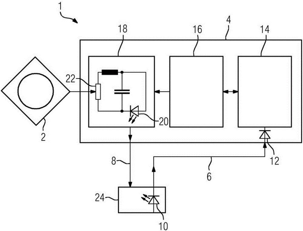
[0023] figure 1 Shown is a device 1 for temperature measurement at a high voltage potential, comprising an optical current transformer 2, an electronic temperature sensor 4, a first and a second optical waveguide 6, 8 and a first light emitting diode 10, which is located at ground Within station 24. In addition, the temperature sensor 4 includes exactly one photodiode 12 , a capacitor 14 , a control unit 16 and an oscillation circuit 18 . Furthermore, the second LED 20 and the temperature-sensing resistor 22 are located in the current loop of the oscillator circuit 18 . Here, the temperature sensing resistor 22 can be, for example, a thermistor, a PT100, a thermal element or a semiconductor sensor.

[0024] Light from the first light emitting diode 10 is conducted via the first optical waveguide 6 to the photodiode 12 in the electronic temperature sensor 4 . The optical waveguides 6, 8 may preferably be standard multimode optical waveguides or 200 / 220 μm Hard-Cladding-Silic...


PUM

PropertyMeasurementUnit
Optical poweraaaaaaaaaa

Abstract

Described is an arrangement for temperature measurement at high-voltage potential. The energy for measuring the temperature of an optical current transformer is provided by precisely one photodiode. The photodiode is supplied by means of light from a light source, the light from the light source being guided to the photodiode via an optical waveguide.

Description

technical field [0001] The invention relates to a device for temperature measurement at a high voltage potential using an electronic temperature sensor that measures the temperature of an optical current transformer and is powered by a light source. Background technique [0002] Optical current transformers have been known for a long time. A current transformer is generally understood to be a measuring transducer which has a sensor probe for the potential-free measurement of an alternating current. Optical current transformers are used to measure the Faraday effect. The Faraday effect describes the polarization rotation of a linearly polarized electromagnetic wave as it passes through a transparent medium on which a temporally constant magnetic field parallel to the direction of propagation of the wave is applied. [0003] Optical current transformers are also increasingly being used for high voltage potentials. Such an optical current transformer is disclosed, for exampl...

Claims


Application Information

Patent Timeline
IPC IPC(8): G01K7/20G01K7/24
CPCG01K7/203G01K7/245G01K2215/00G01K7/20G01K7/22G01K13/00
Inventor M.里克特M.威尔施
Owner SIEMENS ENERGY GLOBAL GMBH CO & KG
Why Eureka
Try Eureka