
Method for generating and controlling charging and discharging pulses of pulse charging device

A pulse charging and discharging pulse technology, applied in circuit devices, battery circuit devices, current collectors, etc., can solve the problems of complex charging output circuit, high manufacturing and maintenance costs

Inactive Publication Date: 2011-08-03
肖相如
View PDF4 Cites 41 Cited by
  • Summary
  • Abstract
  • Description
  • Claims
  • Application Information

AI Technical Summary

Problems solved by technology

The present invention aims at innovating the existing charging mode including the use of foreign relatively advanced charging dedicated control integrated circuits or the pulse charging technology of single-chip microcomputers. The output pulses of the switching transformers must first be rectified and filtered into DC voltages and then converted into pulses, so as to solve this problem. The charging output circuit of the charging mode must be connected in series with power transistors, which leads to the problems of relatively complicated charging output circuit and relatively high manufacturing and maintenance costs; there is no solution to the existing technical solution of using the secondary winding of the switching transformer to output pulse rectification to charge the battery The technical problem of synchronous alternation of discharge pulses and charge pulses

Method used


Image

  • Method for generating and controlling charging and discharging pulses of pulse charging device
  • Method for generating and controlling charging and discharging pulses of pulse charging device
  • Method for generating and controlling charging and discharging pulses of pulse charging device

Examples


Embodiment Construction

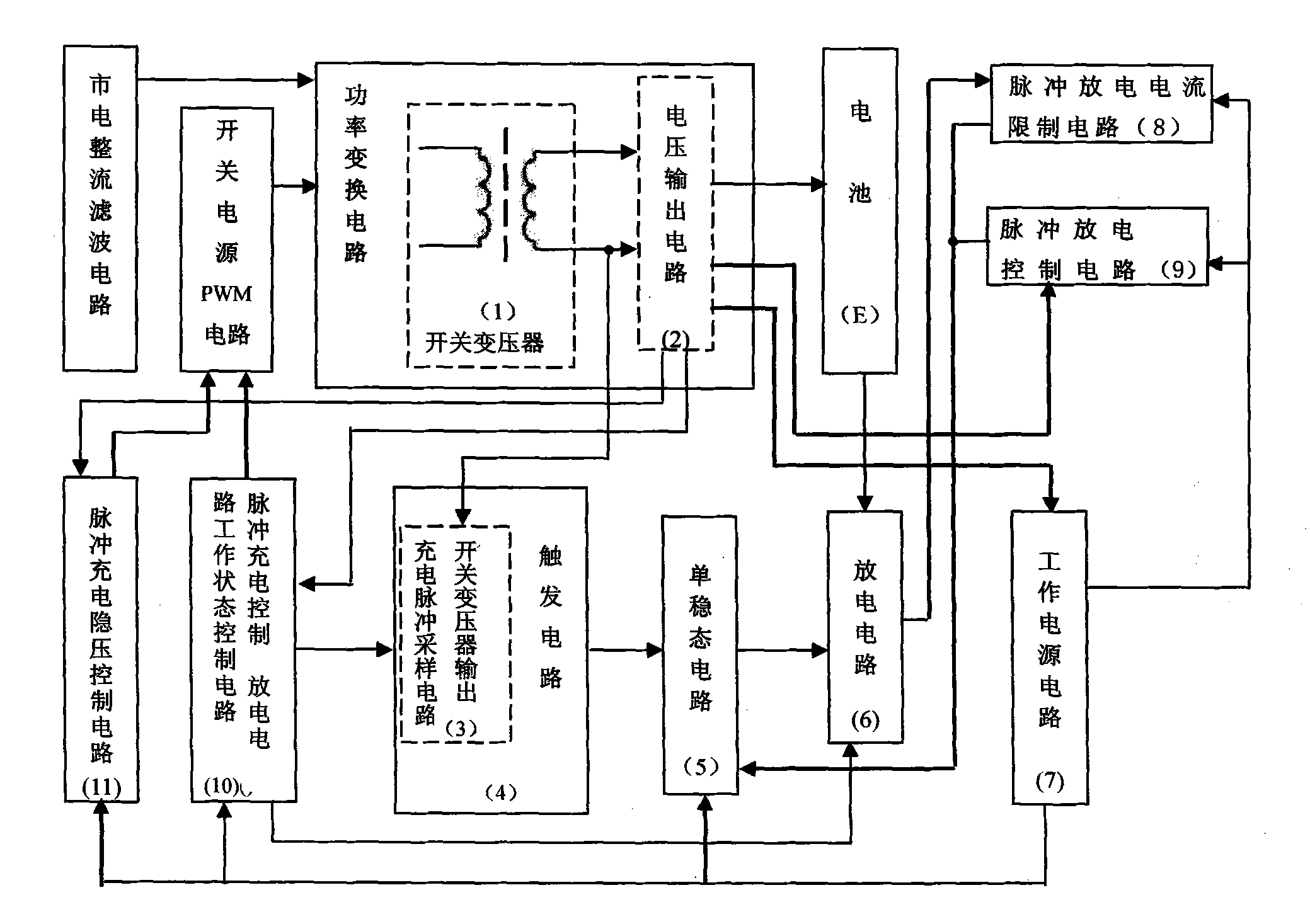
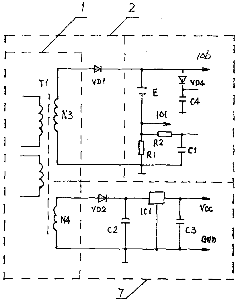
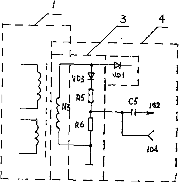
[0072] A pulse charging device designed by applying this method, the circuit diagram is as follows Figure 9 As shown, the switching power supply adopts a single-ended flyback power conversion topology, adopts a three-stage charging (pulse constant current charging, pulse constant voltage charging, pulse trickle charging) control method and a charging control circuit composed of a general integrated circuit. The charging device is composed of a mains rectification and filtering circuit, a PWM circuit, a power conversion circuit and a charging pulse voltage output circuit, a working power circuit, a pulse charging voltage stabilization control circuit, a pulse charging control and status display circuit, and a monostable circuit based on a time base circuit. State circuit, switching transformer secondary winding output charge pulse sampling and monostable trigger circuit, pulse discharge circuit, pulse discharge current limiting circuit, pulse discharge control circuit, pulse di...


PUM


Abstract

The invention discloses a method for generating and controlling charging and discharging pulses of a pulse charging device. The invention belongs to a pulse charging technology based on a switch power supply. In order to innovate the conventional mode that a pulse voltage is rectified and filtered into a direct current voltage and the direct current voltage is then converted into a pulse in outputting of the charging pulse by adopting the pulse charging technology of a foreign special charging control integrated circuit, and to solve the problem that a switch transformer is adopted to output pulse charging and to generate the discharging pulse simultaneously, a method for adopting a secondary winding of the switch transformer to output the pulse charging and introduce outputting of the charging pulse to trigger a single steady-state circuit which is formed on the basis of a time-base circuit to convert into outputting of the discharge pulse which is alternated simultaneously with the charging pulse in a temporary steady state is provided, and the method for automatically regulating a control end voltage of the time-base circuit to control the discharge pulse and improving the conventional charging control circuit and a voltage stabilizing circuit to control the charging pulse is provided. The method provided by the invention is applied to charging of a lead acid battery, and charging effects on other batteries are required for further test.

Description

1. Technical field [0001] The invention belongs to the pulse charging technology based on a switching power supply, and in particular relates to a method for outputting pulse charging and generating a discharge pulse from a secondary winding of a switching transformer using a switching power supply of a charging device and a control method for charging and discharging pulses. 2. Background technology [0002] (1) The existing relatively advanced charging and discharging pulse generation and control methods and charging ASICs have made important technological progress and superior performance, but there are deficiencies, and some technical solutions have unresolved key points Problem; the present invention has substantial innovation over the prior art [0003] There are mainly two modes in the existing pulse charging mode, one is a cycle including pulse charging-stop charging two stages, the other is a cycle including positive pulse charging-negative pulse instantaneous disch...

Claims


Application Information

Patent Timeline
IPC IPC(8): H02J7/00H02J7/10
Inventor 肖相如
Owner 肖相如
Learn More