Piezoelectric vibrating reed, piezoelectric vibrator, method for manufacturing piezoelectric vibrator, oscillator, electronic apparatus, and radio-controlled timepiece

A piezoelectric vibrating piece and piezoelectric vibrator technology, which is applied in the field of radio clocks, can solve the problems of reduced production efficiency, difficulty in maintaining joint strength, and deviation of joint strength, etc., and achieve the effect of increased yield and stable quality

Inactive Publication Date: 2011-08-03
SEIKO INSTR INC
View PDF2 Cites 5 Cited by
  • Summary
  • Abstract
  • Description
  • Claims
  • Application Information

AI Technical Summary

Problems solved by technology

[0008] However, in the above-mentioned conventional ultrasonic bonding piezoelectric vibrator, the bonding strength between the bump and the piezoelectric vibrating piece (mounting electrode) tends to vary, and it is difficult to maintain a stable bonding strength.
[0009] Therefore, in order to ensure the bonding strength between the bumps and the piezoelectric vibrating reed, it is conceivable to adopt a method of forming multiple bumps at one bonding point and performing ultrasonic bonding, but there is a problem that the production efficiency decreases

Method used


Image

  • Piezoelectric vibrating reed, piezoelectric vibrator, method for manufacturing piezoelectric vibrator, oscillator, electronic apparatus, and radio-controlled timepiece
  • Piezoelectric vibrating reed, piezoelectric vibrator, method for manufacturing piezoelectric vibrator, oscillator, electronic apparatus, and radio-controlled timepiece
  • Piezoelectric vibrating reed, piezoelectric vibrator, method for manufacturing piezoelectric vibrator, oscillator, electronic apparatus, and radio-controlled timepiece

Examples


Embodiment Construction

[0049] Below, refer to Figure 1 to Figure 25 , the embodiment of the present invention will be described. In addition, in this embodiment, a case of a piezoelectric vibrator using a tuning-fork type piezoelectric vibrating reed will be described.

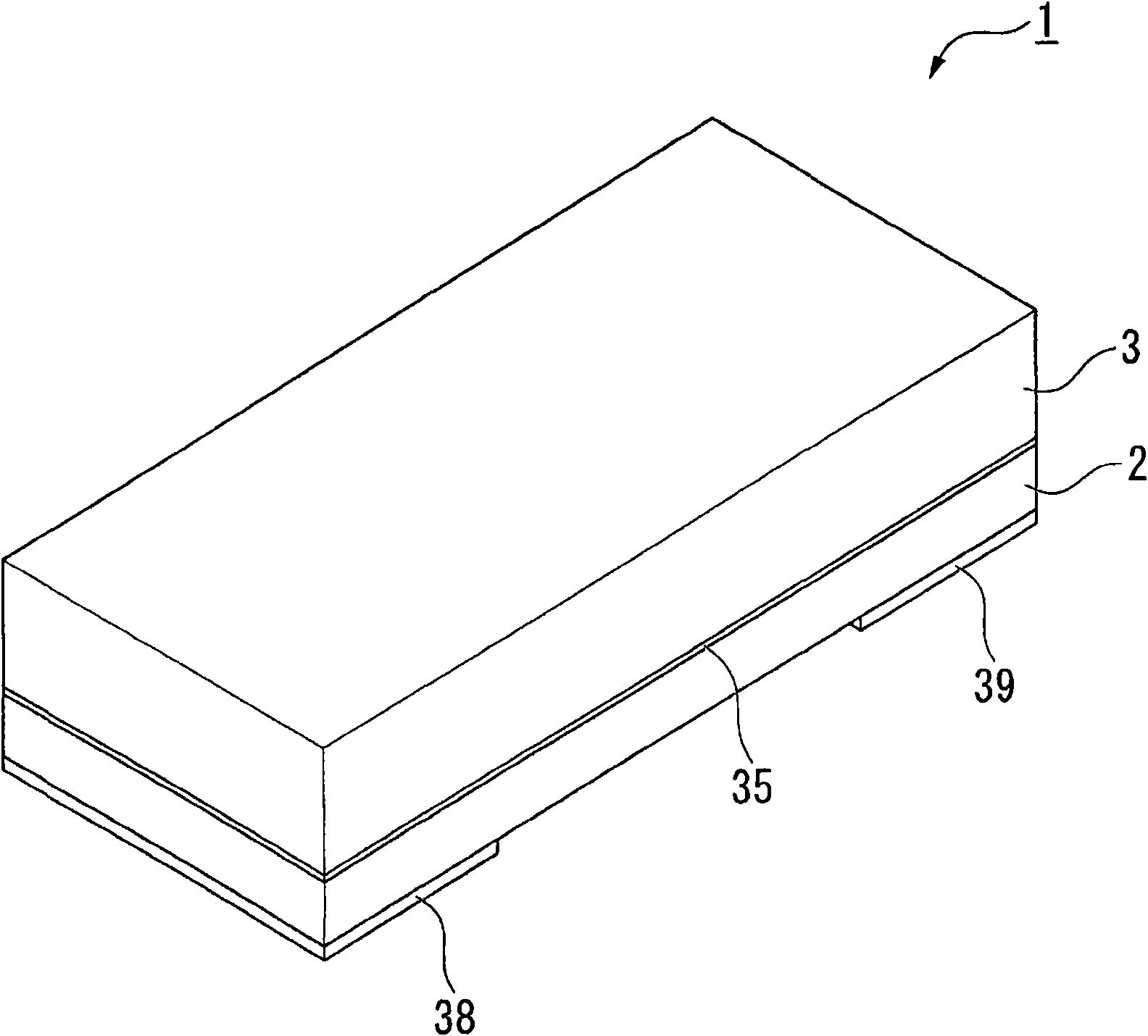
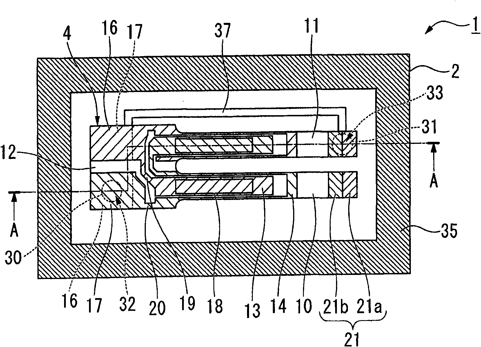
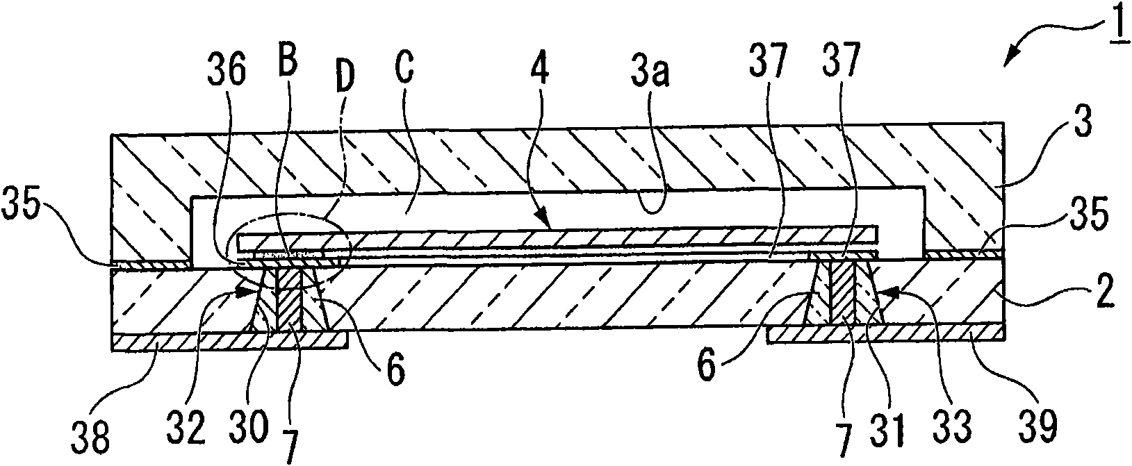
[0050] Such as Figure 1 to Figure 4 As shown, the piezoelectric vibrator 1 of this embodiment is formed in a box shape in which two layers of a base substrate 2 and a lid substrate 3 are stacked, and is a surface mount type in which a piezoelectric vibrating reed 4 is accommodated in an internal cavity C. piezoelectric vibrator. In addition, in Figure 4 For convenience of illustration, illustration of excitation electrode 15 , extraction electrodes 19 , 20 , mounting electrodes 16 , 17 , and weight metal film 21 , which will be described later, is omitted.

[0051] Such as Figure 5 to Figure 7 As shown, the piezoelectric vibrating piece 4 is a tuning-fork type vibrating piece formed of a piezoelectric material such as cryst...


PUM


Abstract

The present invention provides a piezoelectric vibrating reed capable of securing a stable bonding strength between a bump and the piezoelectric vibrating reed, a piezoelectric vibrator, a method for manufacturing the piezoelectric vibrator, and an oscillator, an electronic apparatus, and a radio-controlled timepiece. The piezoelectric vibrating reed (4) includes: a vibrating portion; a base portion (12) adjacent to the vibrating portion; excitation electrodes formed in the vibrating portion; mount electrodes (16, 17) formed in the base portion; and extraction electrodes for electrically connecting the excitation electrodes and the mount electrodes to each other. A bonding film (72) made of gold is formed on the surfaces of the mount electrodes, and the bonding film is formed to a thickness such that, when the bonding film is ultrasonically bonded to a bump (B) made of gold, mutual diffusion occurs over approximately the entire area in the thickness direction of the bonding film.

Description

technical field [0001] The invention relates to a piezoelectric vibrating piece, a piezoelectric vibrator, a manufacturing method of the piezoelectric vibrator, an oscillator, electronic equipment and a radio clock. Background technique [0002] Conventionally, a piezoelectric vibrator in which a pair of substrates are bonded and a piezoelectric vibrating reed is sealed in a cavity formed between the substrates is widely known. The piezoelectric vibrator is used, for example, as a time source of a mobile phone or a portable information terminal, a timing source of a control signal, a reference signal source, and the like. Various piezoelectric vibrators are known as forms of the piezoelectric vibrator, and a surface mount type piezoelectric vibrator is known as one of them. [0003] As a surface mount type piezoelectric vibrator, there is a two-layer structure type piezoelectric vibrator in which a base substrate and a lid substrate are directly bonded and a piezoelectric v...

Claims


Application Information

Patent Timeline
Patent Type & Authority Applications(China)
IPC IPC(8): H03H9/21H03H3/02G04C9/02H03H3/04H03H9/02H03H9/10H03H9/19
CPCH01L41/053H03B5/32H01L41/22H03H9/1021H03H3/02H03H9/21H03H2003/026Y10T29/42
Inventor 福田纯也
Owner SEIKO INSTR INC
Why Eureka
Try Eureka