Error code testing system based on FPGA (Field Programmable Gate Array)

A bit error testing and bit error technology, applied in the field of communication, can solve the problems of complex implementation structure and long synchronization time, and achieve the effect of improving flexibility

Active Publication Date: 2011-08-03
SOURCE PHOTONICS CHENGDU
View PDF1 Cites 15 Cited by
  • Summary
  • Abstract
  • Description
  • Claims
  • Application Information

AI Technical Summary

Problems solved by technology

However, these methods have disadvantages such as

Method used


Image

  • Error code testing system based on FPGA (Field Programmable Gate Array)
  • Error code testing system based on FPGA (Field Programmable Gate Array)
  • Error code testing system based on FPGA (Field Programmable Gate Array)

Examples


Embodiment Construction

[0033] The present invention will be further described below in conjunction with accompanying drawing and specific implementation;

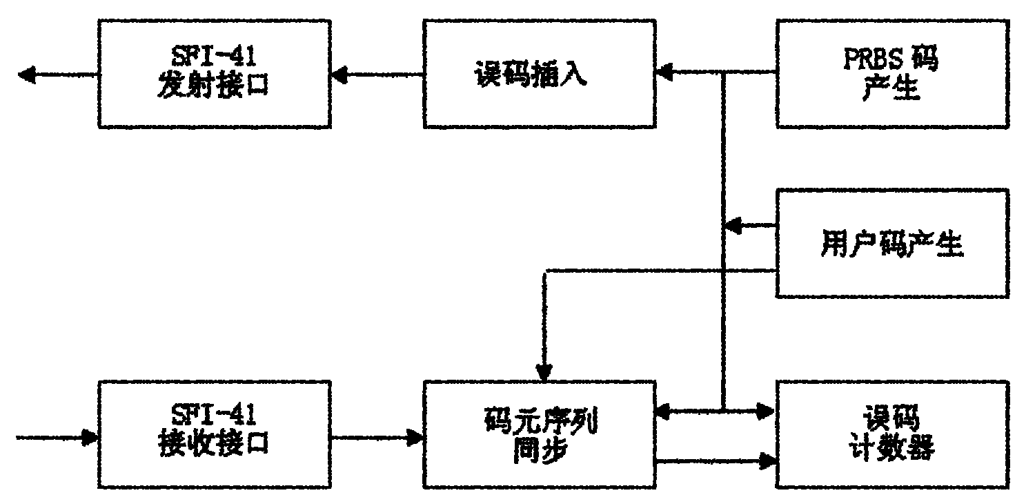
[0034] see figure 1 The functional block diagram of the FPGA bit error test is shown. It includes SFI-41 receiving interface, symbol sequence synchronization module, error counter, user code generating module, PRBS module, error inserting module and SPF-41 transmitting interface.

[0035] The symbol sequence synchronization module is used to realize the synchronization between the received symbol and the local symbol; the error counter is used to count the number of symbol errors in a certain period of time; the user code generation module is used to generate custom codes; PRBS The module generates PRBS symbols; the bit error insertion module is used for the sending end to insert bit errors into the data.

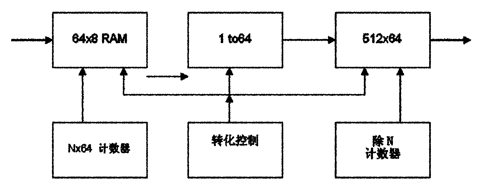
[0036] based on figure 1 In the bit error test method of FPGA shown above, high-speed data is converted to serial and parallel before ente...


PUM


Abstract

The invention discloses an error code testing system based on an FPGA (Field Programmable Gate Array), which comprises a code element sequence synchronization module, an error code counter, a user code generation module and a PRBS (Pseudo Random Binary Sequence) module, wherein the code element sequence synchronization module is used for realizing the synchronization of a receiving code element and a local code element; the error code counter is used for counting number of code element errors in same time period; the user code generation module is used for generating a custom code; and the PRBS module is used for generating a PRBS code element. The error code testing system disclosed by the invention improves the principles of the traditional circuit, apparatus and communication protocol design by applying integration and flexibility of the FPGA, and can be applied to a production line and research and development to be used as a main control chip of an error code testing apparatus.

Description

technical field [0001] The invention relates to the communication field, in particular to an FPGA-based error code testing system. Background technique [0002] With the rapid development of information today, communication has undoubtedly become an indispensable part of people's lives. Especially digital communication, it has become an important means of modern information transmission due to its strong anti-interference ability, high-quality long-distance transmission, easy connection with computers, and easy encryption. Digital communication has developed by leaps and bounds. The reliability of its transmission is particularly important. At the same time, due to the development of integrated circuits, FPGA has also developed rapidly, and its application scope is becoming wider and wider. However, due to the relatively high overall cost, FPGA is mainly used in high-end fields such as aerospace, instrument manufacturing, and communications. Due to the progress and improv...

Claims


Application Information

Patent Timeline
IPC IPC(8): H04L12/26
Inventor 朱富向刚
Owner SOURCE PHOTONICS CHENGDU
Why Eureka
Try Eureka