Path computing method and unit in optical network

A technology of path calculation and optical network, applied in the field of communication, can solve the problem of no ring topology information and so on

Active Publication Date: 2011-08-03
HUAWEI TECH CO LTD
View PDF6 Cites 8 Cited by
  • Summary
  • Abstract
  • Description
  • Claims
  • Application Information

AI Technical Summary

Problems solved by technology

[0006] Although the nodes or PCEs in the optical network in the prior art can calculate the path with ring protection capability, the calculated path is not the optimal path because there is no specific ring topology information

Method used


Image

  • Path computing method and unit in optical network
  • Path computing method and unit in optical network
  • Path computing method and unit in optical network

Examples


example 1

[0104] Example 1: 2-fiber MS-SPRING

[0105] Taking the 2-fiber multiplex section ring in the SDH network as an example, in a pair of optical fibers with opposite directions between adjacent nodes, half of the time slots are used as the working path to transmit bidirectional services; the other half of the time slots are used as the protection path (that is, these The protection type of the timeslot is ring protection), when there is no fault in the ring, additional services that can be preempted can be transmitted; when the ring fails, the services in the working path can preempt the additional services and switch to the protection path for transmission.

[0106] Such as Figure 7 As shown, assuming that the bandwidth of the link is STM-16 (Synchronous Transfer Mode-16, Synchronous Transfer Mode-16), there are two ways to publish link information:

[0107]Solution 1: The working path part of a pair of optical fibers can be bound as one TE link, and the protection path part c...

example 2

[0135] Example 2: 4-fiber MS-SPRING

[0136] The 4-fiber multiplex section ring is similar to the 2-fiber multiplex section ring. The main difference is that between adjacent nodes, the working path and protection path in the same direction are transmitted by two optical fibers instead of the same optical fiber. different time slots to transmit.

[0137] Such as Figure 8 As shown, similar to Example 1, the working path in two directions can be regarded as one TE link; the protection path in two directions can be regarded as another TE link; the four optical fibers can also be regarded as one There are two TE links, and two Link Protection Type Sub-TLVs are used to distinguish the working path and the protection path.

example 3

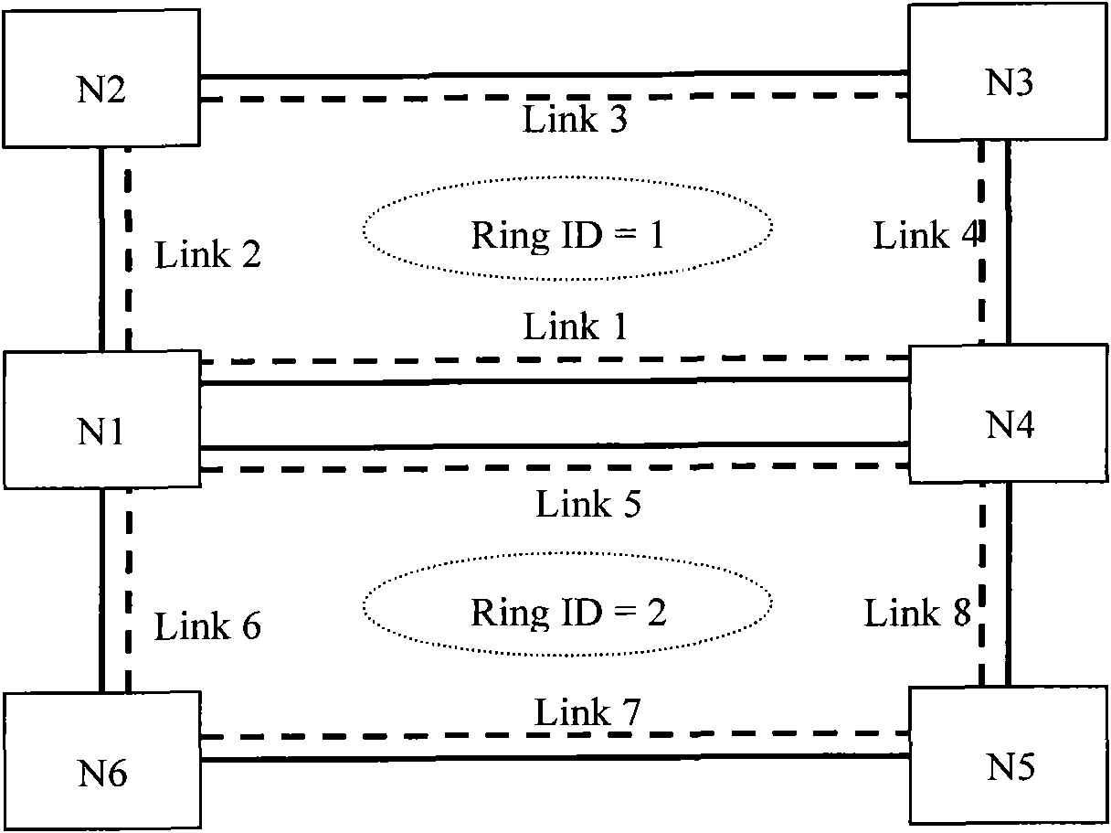
[0138] Example 3: Multi-ring shared optical fiber

[0139] When two rings share a pair of optical fibers and different rings use different time slots of the optical fibers, it is necessary to specify which time slots belong to which ring when the routing protocol publishes link information.

[0140] Such as Figure 9 As shown, it is assumed that there are two 2-fiber multiplex section rings in the network, and the optical fiber between A-B is STM-16, and the time slots 1-8 of each fiber are used by ring Ring1 (time slots 1-4 are working path, time slots 5-8 are protection paths), and time slots 9-16 are used by Ring2 (time slots 9-12 are working paths, and time slots 13-16 are protection paths).

[0141] There are also multiple routing publishing schemes:

[0142] Solution 1: You can bind W1+W2 of Ring1, P1+P2 of Ring1, W1+W2 of Ring2, and P1+P2 of Ring2 into four TE links respectively, and assign a link ID to each TE link distinguish. In this case, the protection type of ...


PUM


Abstract

The invention discloses a path computing method and unit in an optical network. The method comprises the following steps: releasing ring protection information of each link in the optical network by a routing protocol message, wherein the ring protection information comprises the identification of each link and the identification of a ring to which each link belongs; receiving the ring protectioninformation by the routing protocol message, and according to the ring protection information, combining the links with the same ring identification into a ring so as to obtain ring topology information; and according to the ring topology information, carrying out path computing. Compared with the prior art, an optimal path can be computed by using the method and unit provided by the invention.

Description

technical field [0001] The invention relates to the field of communication technology, in particular to a path calculation method and a path calculation unit in an optical network. Background technique [0002] The traditional optical network is a system based on centralized management. Optical connections are established between optical network nodes in a permanent connection mode, and manual intervention is required for the creation, maintenance, and removal of optical connections. As the type and quantity of services carried by optical networks continue to grow, traditional optical networks cannot meet the requirements of dynamic and flexible networking. [0003] In order to solve this problem, the ITU-T proposed an ASON (Automatically Switched Optical Network, Automatically Switched Optical Network) architecture. ASON is based on a mesh (MESH) network topology, adding a control plane to the traditional optical network. The optical network node first obtains the connec...

Claims


Application Information

Patent Timeline
IPC IPC(8): H04Q11/00H04L12/56
CPCH04J2203/0053H04L45/62H04J3/085H04J2203/006H04L12/437
Inventor 章发太林毅
Owner HUAWEI TECH CO LTD
Why Eureka
Try Eureka