
Repeated foaming device for gathering and delivering pipeline of foam drainage gas-production well

A foam drainage and gas recovery technology, which is applied in the direction of mining fluid, earthwork drilling, wellbore/well components, etc., can solve problems such as liquid accumulation in pipelines, serious gas-liquid stratification, and blockage of gathering and transportation pipelines, so as to avoid pipeline blockage , reduce mining costs, and reduce the effect of gas-liquid stratification

Inactive Publication Date: 2011-08-10
SOUTHWEST PETROLEUM UNIV
View PDF5 Cites 12 Cited by
  • Summary
  • Abstract
  • Description
  • Claims
  • Application Information

AI Technical Summary

Problems solved by technology

[0006] The purpose of the present invention is: to solve the problem of foamy fluid foam bursting in the surface gathering and transportation pipeline of the foam drainage gas production well, serious gas-liquid stratification, poor gas carrying water, serious liquid accumulation in the pipeline, easy to cause blockage of the gathering and transportation pipeline, and seriously affect the To deal with the problem of normal production of gas wells, we provide a repeated foaming device for surface gathering and transportation pipelines of foam drainage gas production wells

Method used


Image

  • Repeated foaming device for gathering and delivering pipeline of foam drainage gas-production well
  • Repeated foaming device for gathering and delivering pipeline of foam drainage gas-production well

Examples


Embodiment Construction

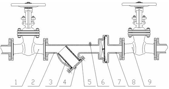
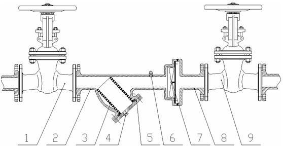
[0012] According to the drawings, one end of the inlet gate valve 1 of a foaming exhaust well collection and transportation pipeline is connected to the upstream collection and transportation pipeline with a flange; the other end of the inlet gate valve 1 is connected to the device shell A2 through a flange; There is a flange cover 5 under the device housing A2, and a drain valve 4 is installed on the flange cover 5. One end of the filter cartridge 3 is placed at the inlet end of the device housing A2, and the other end is placed on the drain valve in the device housing A2. 4, the solid-phase impurities in the collection and transportation pipeline are filtered through the filter cartridge 3, and the filtered solid-phase impurities can be discharged by the sewage valve 4; a hydraulic quick joint 6 is installed above the device housing A2, and the foaming agent outside the collection and transportation pipeline is injected The equipment can inject foaming agent into the collecti...


PUM


Abstract

The invention relates to a repeated foaming device for a gathering and delivering pipeline of a foam drainage gas-production well in the natural gas gathering and delivering process. The repeated foaming device can solve the difficulty that natural production of a gas well is influenced by liquid accumulation, even blockage of the gathering and delivering pipeline, caused by foam burst and gas-liquid layering in the the gathering and delivering pipeline of the foam drainage gas-production well. A technical scheme of the invention is that an inlet gate valve is connected with an upstream gathering and delivering pipeline; the other end of the inlet gate valve is connected with a device housing A; a flange cover is arranged below the device housing A; a blowoff valve is arranged on the cover; one end of a filter cartridge is connected with an inlet of the device housing A while the other end thereof is connected with the blowoff valve; a hydraulic quick joint is mounted above the device housing A; a stirring blade is mounted on an outlet of the device housing A; an inlet end of a device housing B is connected with an outlet end of the device housing A; an outlet end of the device housing B is connected with an outlet gate valve; and the other end of the outlet gate valve is connected with a downstream gathering and delivering pipeline. By using the invention, a foaming agent can be injected into the gathering and delivering pipeline so that the accumulated liquid in the pipeline can foam again; moreover, solid-phase impurities in the pipeline is filtered to be removed so as to avoid gas-liquid layering and pipeline blockage.

Description

technical field [0001] The invention relates to a repeated foaming device for a gathering and transportation pipeline of a foam drainage gas production well. technical background [0002] With the prolongation of the development time of natural gas wells, water production from gas wells is an inevitable phenomenon. After a certain stage of gas well production with water, due to the continuous decrease of gas-liquid ratio, the accumulation of liquid at the bottom of the well has seriously affected the normal production of the gas well, and even caused The root cause of stop spraying. [0003] Gas well drainage and gas recovery technologies include various mature technologies such as gas lift, bubble drainage, and downhole restrictors. For the medium and low pressure gas wells that still have the energy to produce water, but it is obviously found that the water is not smooth, the foaming agent is injected into the annular space of the tubing and casing, and the water is foame...

Claims


Application Information

Patent Timeline
IPC IPC(8): E21B43/16E21B43/22
Inventor 梁政邓雄王飞蒋发光张梁赵广慧
Owner SOUTHWEST PETROLEUM UNIV
Learn More