
Optical fibre plug, optical fibre socket and optical fibre connector

A technology of optical fiber plug and optical fiber socket, which is applied in the coupling of optical waveguide and other directions, can solve the problems of optical signal loss, optical axis misalignment, and reduced signal transmission performance of optical fiber coupling connectors, so as to achieve accurate alignment and ensure signal transmission performance effect

Inactive Publication Date: 2011-08-10
HONG FU JIN PRECISION IND (SHENZHEN) CO LTD +1
View PDF7 Cites 21 Cited by
  • Summary
  • Abstract
  • Description
  • Claims
  • Application Information

AI Technical Summary

Problems solved by technology

The socket and plug in the traditional fiber optic connector are respectively provided with a fiber guide hole for accommodating the optical fiber and a lens for collimating or concentrating the optical signal transmitted by the optical fiber. However, since both the socket and the plug are injection molded The manufacturing process is integrally formed. If the center of the guide hole and the optical axis of the lens cannot be aligned accurately, the center of the optical fiber in the guide hole will not be aligned with the optical axis of the lens, which will easily cause optical signal loss and reduce the optical fiber. Signal Transmission Performance of Coupling Connectors

Method used


Image

  • Optical fibre plug, optical fibre socket and optical fibre connector
  • Optical fibre plug, optical fibre socket and optical fibre connector
  • Optical fibre plug, optical fibre socket and optical fibre connector

Examples


Embodiment Construction

[0039] The present invention will be further described in detail below in conjunction with the accompanying drawings.

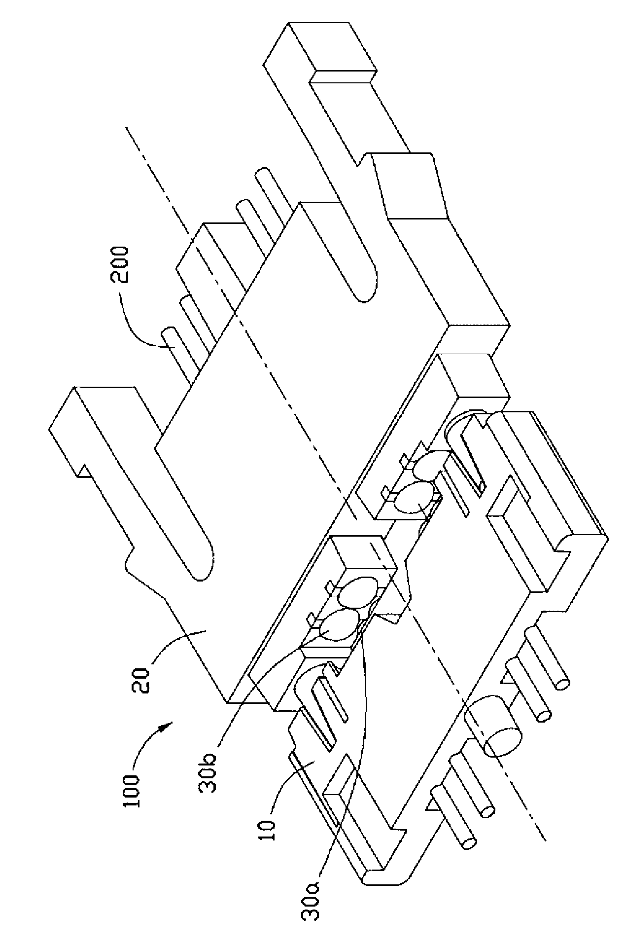
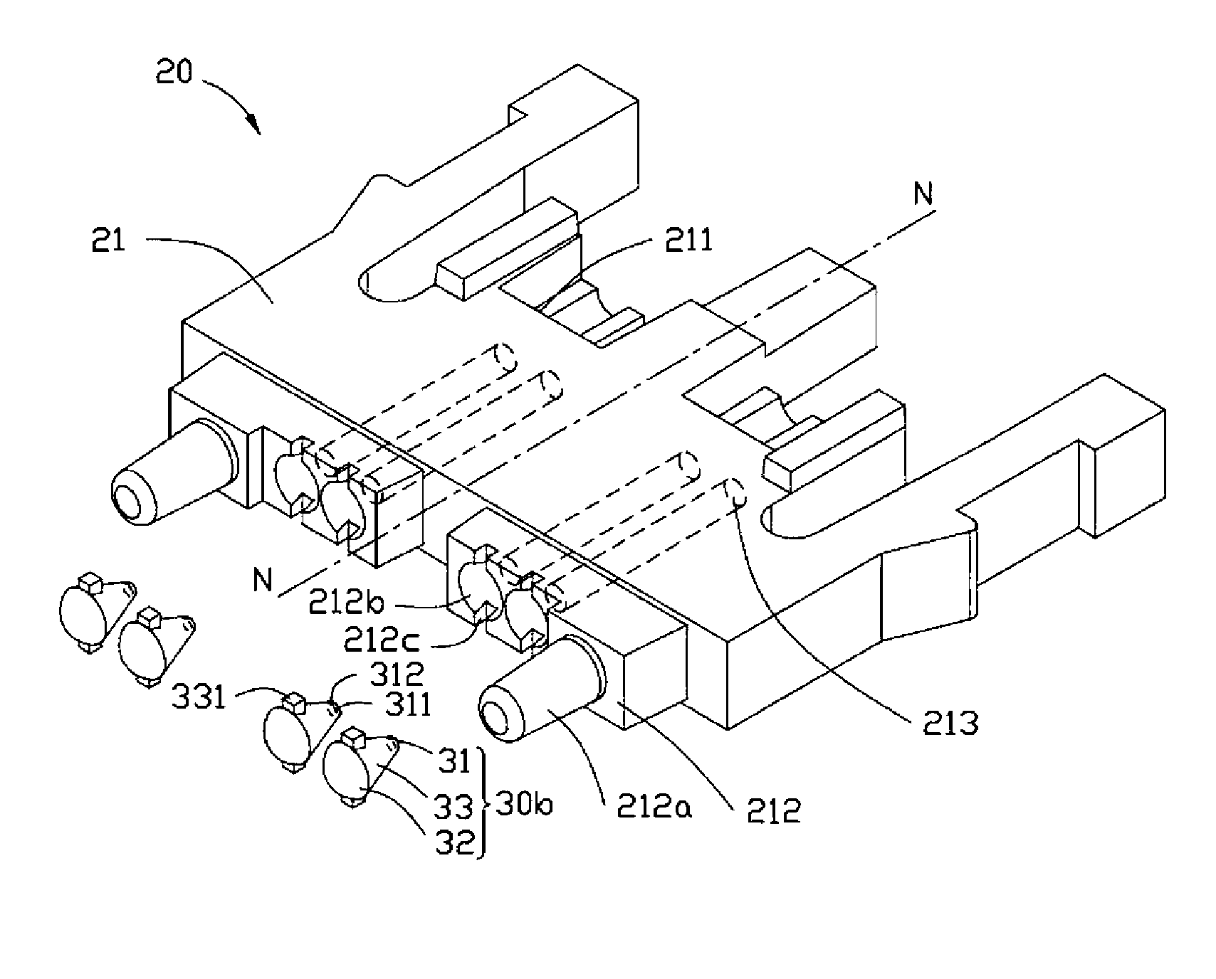
[0040] Such as Figure 1 to Figure 3 As shown, it is an optical fiber connector 100 provided by the embodiment of the present invention, which is used for coupling and connecting an optical fiber 200; The sockets 20 cooperate with each other.

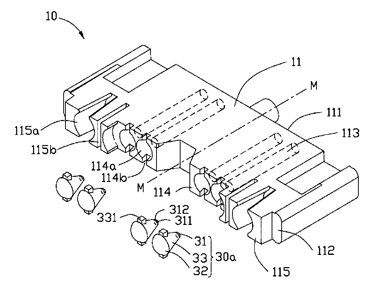
[0041] The fiber optic plug 10 includes a first body 11 and at least one first focusing lens 30a. The first body 11 includes a first end surface 111 , a second end surface 112 opposite to the first end surface 111 , and a symmetry axis M perpendicular to the first end surface 111 and the second end surface 112 . At least one first guide hole 113 extending toward the second end surface 112 along a direction parallel to the axis of symmetry M is defined on the first end surface 111 . In this embodiment, the number of the first guide holes 113 is four and two pairs are symmetrically distributed on both sides of the axi...


PUM


Abstract

The invention provides an optical fibre connector, comprising an optical fibre plug and an optical fibre socket, wherein the optical fibre plug comprises a first body and a first condenser lens; the first body comprises a first end face and a second end face; a first guide hole is disposed on the first end face; a first containing groove, a first location groove and a mounting groove are disposed on the second end face; the optical fibre socket comprises a second body and a second condenser lens; the second body comprises a third end face and a fourth end face; a second guide hole is disposed on the third end face; a second containing groove, a second location groove and a location column are disposed on the fourth end face; the first and second condenser lenses respectively comprise a side face which is provided with a location block; the first and second condenser lenses are respectively contained in the first and second containing grooves; and the location blocks are blocked in the first and second location grooves; the optical fibre plug is connected to the optical fibre socket by the mounting groove and the location column. The bodies are connected to the condenser lenses by the location grooves and the location blocks; and the concentric alignment precision of the guide holes and the condenser lenses is improved.

Description

technical field [0001] The invention relates to a signal transmission device, in particular to an optical fiber plug with better signal transmission performance, an optical fiber socket and an optical fiber connector composed of the optical fiber plug and the optical fiber socket. Background technique [0002] Optical fiber transmission has outstanding advantages such as wide frequency bandwidth, low loss, strong anti-interference ability, high fidelity and reliable working performance. With the continuous decline in the cost of optical fiber, optical fiber has been more and more widely used in data signal transmission technology . [0003] Optical fiber connectors play an important role in optical signal transmission, and the design of optical fiber connectors affects the coupling efficiency of optical fibers. The socket and plug in the traditional fiber optic connector are respectively provided with a fiber guide hole for accommodating the optical fiber and a lens for col...

Claims


Application Information

Patent Timeline
Patent Type & Authority Applications(China)
IPC IPC(8): G02B6/38
Inventor 吴昆展
Owner HONG FU JIN PRECISION IND (SHENZHEN) CO LTD
Learn More