Probe card device and neck-like probe thereof

A probe card and probe technology, applied in the field of probe cards, can solve problems such as hindering the research and development and progress of probe card devices, and achieve the effect of protecting annular insulators

Active Publication Date: 2021-08-06
CHUNGHWA PRECISION TEST TECH
View PDF9 Cites 0 Cited by
  • Summary
  • Abstract
  • Description
  • Claims
  • Application Information

AI Technical Summary

Problems solved by technology

However, the cooperation structure between the above-mentioned conductive needle body and the insulating layer of the existing conductive probes has been established for many years, thus virtually hindering the further development and progress of the existing probe card devices

Method used


Image

  • Probe card device and neck-like probe thereof
  • Probe card device and neck-like probe thereof
  • Probe card device and neck-like probe thereof

Examples


Embodiment 1

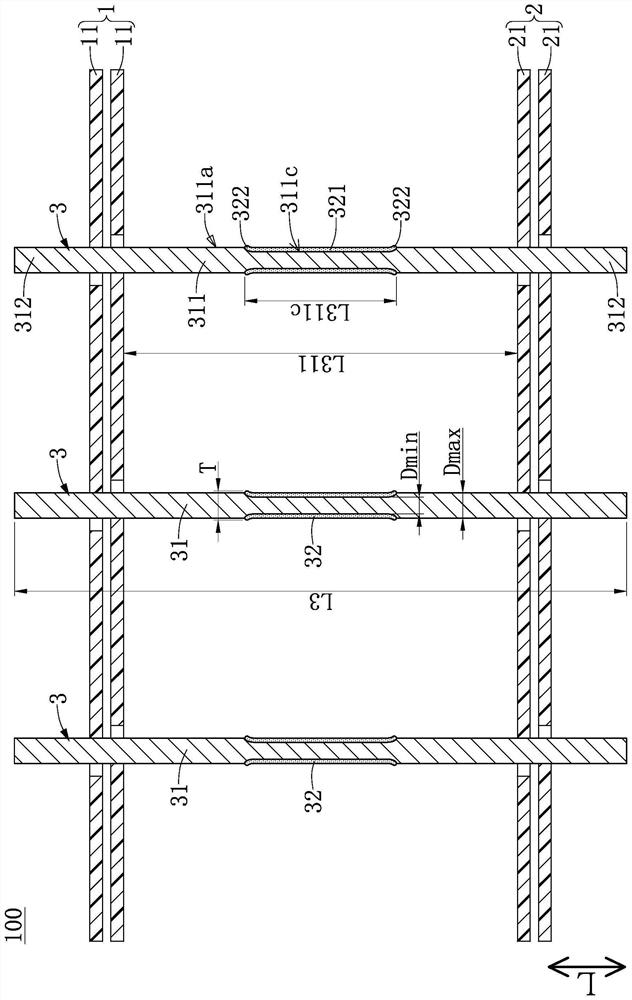
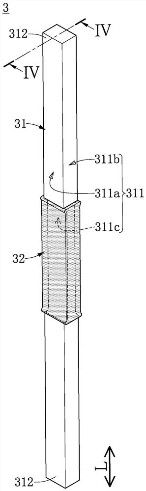
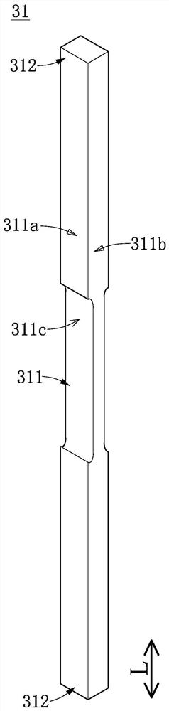
[0034] see Figure 1 to Figure 9 As shown, it is Embodiment 1 of the present invention. Such as Figure 1 to Figure 3 As shown, the present embodiment discloses a probe card device 100, the opposite sides of which can be respectively used to abut against a space transformer and an object under test (such as a semiconductor chip). Wherein, the probe card device 100 includes a first guide plate unit 1, a second guide plate unit 2 spaced apart from the first guide plate unit 1, clamped between the first guide plate unit 1 and the second guide plate A spacer plate (not shown) between the units 2 and a plurality of neck-like probes 3 passing through the first guide plate unit 1 and the second guide plate unit 2 .

[0035] It should be noted that, in this embodiment, the neck-like probe 3 is illustrated as being matched with the first guide plate unit 1 , the second guide plate unit 2 and the spacer plate, but the present invention is not limited thereto. For example, in other em...

Embodiment 2

[0059] see Figure 10 and Figure 11 As shown, it is Embodiment 2 of the present invention. This embodiment is similar to the above-mentioned Embodiment 1, so the similarities between the two embodiments will not be repeated, and the differences between this embodiment and Embodiment 1 are roughly described as follows:

[0060] In this embodiment, the stroke section 311 is further recessed on each of the narrow side surfaces 311b to form a short groove 311d whose two ends respectively communicate with the two long grooves 311c; The long groove 311c and the two short grooves 311d jointly form a rectangular annular groove. In this embodiment, the two long grooves 311c of the stroke section 311 are arranged in mirror image symmetry, and the two short grooves 311d are also arranged in mirror image symmetry, but the present invention is not limited thereto. For example, in other embodiments not shown in the present invention, the two short grooves 311d may also have different dep...


PUM


Abstract

The invention discloses a probe card device and a neck-like probe thereof. The neck-like probe is elongated and comprises a conductive probe body and an annular insulator. The conductive probe body comprises a stroke section and two tail end sections extending from the two ends of the stroke section respectively. The stroke section comprises two wide side faces and two narrow side faces, and each wide side face is concavely provided with a long groove extending from one of the two narrow side faces to the other of the two narrow side faces. The two long grooves are arranged adjacently, and the minimum distance is formed between the two long grooves and is 95% to 75% of the maximum distance between the two wide side faces. The annular insulator surrounds the portion, where the two long grooves are formed, of the conductive probe body, and the neck-like probe has a thickness at the portion, where the two long grooves are formed, of the annular insulator, and the thickness is 85% to 115% of the maximum distance. Therefore, the conductive probe body is provided with the two long grooves, so that the downward pressing force of the conductive probe body is effectively controlled, and the conductive probe body can stably abut against an object to be detected without damaging the object to be detected.

Description

technical field [0001] The invention relates to a probe card, in particular to a probe card device and a neck-like probe. Background technique [0002] The conductive probe of the existing probe card device includes a conductive needle body and an insulating layer formed at the center of the conductive needle body, and the width and thickness of the conductive needle body are approximately the same, so the above-mentioned insulating layer is in the shape of prominent shape. However, the cooperation structure between the above-mentioned conductive needle body and the insulating layer of the existing conductive probes has been established for a long time, thus virtually hindering the further development and progress of the existing probe card device. [0003] Therefore, the inventor believes that the above-mentioned defects can be improved, Naite devoted himself to research and combined with the application of scientific principles, and finally proposed an invention with reas...

Claims


Application Information

Patent Timeline
Patent Type & Authority Applications(China)
IPC IPC(8): G01R1/067G01R1/073
CPCG01R1/06733G01R1/07307
Inventor 李文聪魏逊泰谢开杰苏伟志
Owner CHUNGHWA PRECISION TEST TECH
Why Eureka
Try Eureka