
Glass placement rack for construction engineering

A technology for construction engineering and placing racks, which is applied in the direction of external frames, load hanging components, packaging, etc. It can solve the problems of inability to fold, large volume of glass placing racks, and inability to fix the top and bottom of the glass at the same time, so as to increase friction , reduced size, and stable placement

Active Publication Date: 2021-07-13
中深建业建设集团有限公司
View PDF9 Cites 0 Cited by
  • Summary
  • Abstract
  • Description
  • Claims
  • Application Information

AI Technical Summary

Problems solved by technology

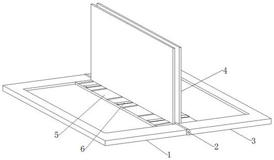
[0004] Based on the technical problems that the glass rack is large and cannot be folded and cannot fix the top and bottom of the glass at the same time, the present invention proposes a glass rack for construction engineering

Method used


Image

  • Glass placement rack for construction engineering
  • Glass placement rack for construction engineering
  • Glass placement rack for construction engineering

Examples


Embodiment 1

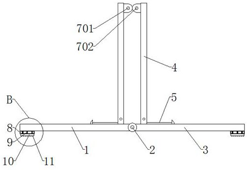
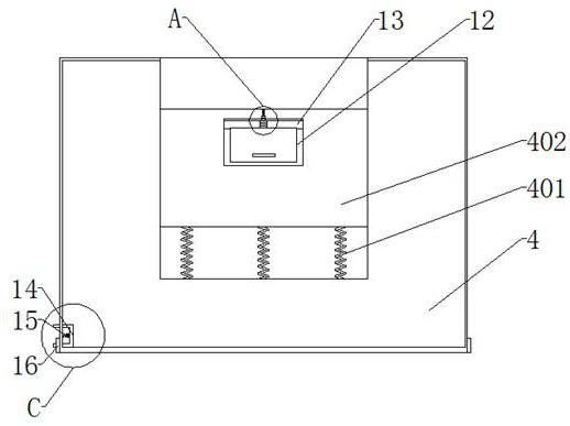
[0030] refer to Figure 1-7 , a glass placement frame for construction engineering, comprising a first bottom plate 1 and a second bottom plate 3, a first rotating shaft 2 is arranged between the first bottom plate 1 and the second bottom plate 3, and the first bottom plate 1 and the second bottom plate 3 are connected to each other. The first rotating shaft 2 is rotationally connected, and one side of the first bottom plate 1 and the second bottom plate 3 is provided with an opening, and the first bottom plate 1 and the second bottom plate 3 are all provided with a first slideway on the inner walls of both sides of the opening. Both the base plate 1 and the second base plate 3 are provided with a number of circular grooves at the first slideway, and the first base plate 1 and the second base plate 3 are all provided with a fixed structure at the first slideway, and the fixed structure includes a first sliding plate 4 and the fixed plate 5, the fixed plate 5 is fixedly connect...

Embodiment 2

[0039] refer to Figure 8 , a kind of glass placement frame for construction engineering. Compared with Embodiment 1, in order to facilitate the transportation of glass to high places, the device in this embodiment is more stable. One side of the first connecting shaft 701 and the second connecting shaft 702 are welded with For the same connecting plate 17, a cross bar 18 is welded between the inner walls of the two connecting plates 17, and an annular groove is opened in the middle of the cross bar 18. When the glass needs to be transported to a high place, the glass needs to be transported by a crane. The outside of the rod 18 is provided with an annular groove, which is more stable and convenient for transportation when transported by a crane.

[0040] When in use, by rotating the first sliding plate 4, the fixed plate 5 changes the angle with the rotation of the first sliding plate 4, and the glass is placed on the fixed plate 5, so that the bottom end of the glass can be ...


PUM


Abstract

The invention belongs to the technical field of construction engineering, in particular to a glass placement rack for construction engineering. In view of the technical problems that the glass placement rack is large in volume and cannot be folded and cannot be fixed at the top and bottom of the glass at the same time, the following solutions are now proposed, including a first bottom plate and a second bottom plate, a first rotating shaft is arranged between the first bottom plate and the second bottom plate, the first bottom plate and the second bottom plate are both rotatably connected with the first rotating shaft, and one of the first bottom plate and the second bottom plate is There are openings on the sides, the first bottom plate and the second bottom plate are both provided with first slideways on the inner walls of both sides of the opening, and the first bottom plate and the second bottom plate are provided with several circles at the first slideway. shaped groove. The present invention can fold the device through the rotation of the first bottom plate and the second bottom plate, thereby reducing its volume and the space occupied when it is not in use, and the device can simultaneously fix the top and bottom ends of the glass through the fixing structure , thus making the glass more stable during transportation.

Description

technical field [0001] The invention relates to the technical field of construction engineering, in particular to a glass placement rack for construction engineering. Background technique [0002] In construction projects, it is often necessary to install glass after the construction of the house is completed. The glass needs to be transported to the construction site by a transport vehicle. The glass is usually placed on the ground. Because the surface of the glass is smooth, it is very inconvenient to take the glass. [0003] After searching, the Chinese patent application number is 201710179325.4, which discloses a glass placement frame, including a bottom frame, a bar, a support bar, a support bar and a crosspiece. A glass placement rack in the above-mentioned patent has the following disadvantages: the bottom end of the glass is clamped by the lever to maintain the stability of the glass placement, but it does not fix the top of the glass, and the top of the glass may n...

Claims


Application Information

Patent Timeline
Patent Type & Authority Patents(China)
IPC IPC(8): B65D85/48B65D61/00B66C1/66
CPCB65D61/00B65D85/48B66C1/66
Inventor 冼玉荣莫汝妹张正姚艺林吴坚民陈华晓余良
Owner 中深建业建设集团有限公司
Learn More