Prepreg spliced by regional glass fiber cloth, PCB and splicing method
A technology of prepreg and glass fiber cloth, which is applied in the direction of printed circuit components and conductive pattern formation, etc., can solve the problem of high production cost of prepreg, achieve the effect of taking into account integrity and reducing production cost
- Summary
- Abstract
- Description
- Claims
- Application Information
AI Technical Summary
Problems solved by technology
Method used
Image
Examples
Embodiment 1
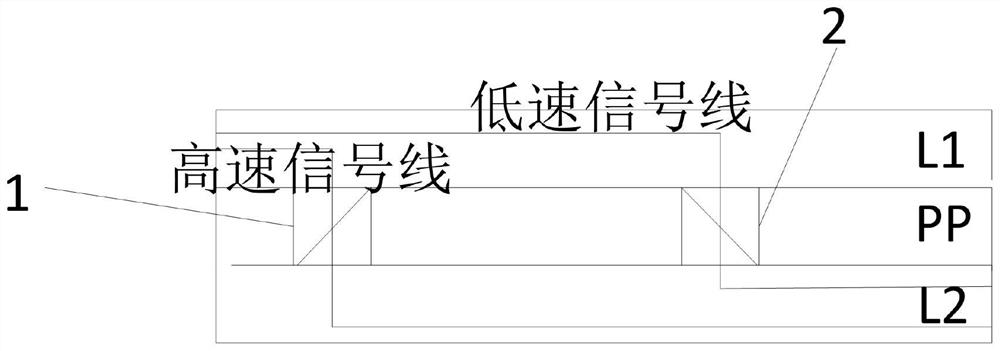
[0030] Such as figure 2 As shown, the present invention provides a prepreg spliced with glass fiber cloth in different regions, which is located between the first wiring layer L1 and the second wiring layer L2 adjacent to the first wiring layer L1, including: the first glass Fiber cloth 1 and second glass fiber cloth 2, the first glass fiber cloth 1 is located in the area where high-speed signal lines pass through the prepreg (PP), and the second glass fiber cloth 2 is located in the area where low-speed signal lines pass through the prepreg, where the high-speed signal The line is a high-speed signal routing path that communicates with the second wiring layer L2 through a via hole in the first wiring layer L1, and the low-speed signal line is a communication path between the first wiring layer L1 and the second wiring layer L2 through a via hole. For the connected low-speed signal routing path, the cost of the first glass fiber cloth 1 is greater than that of the second gl...
Embodiment 2
[0035] The technical solution of the present invention also provides a PCB board, including several prepregs spliced with sub-regional glass fiber cloths according to Embodiment 1.
[0036] The prepregs between adjacent wiring layers that are communicatively connected to each other are prepregs spliced with glass fiber cloth in different areas.
[0037] In particular, if the communication connection between the first wiring layer and the second wiring layer, and the first wiring layer and the second wiring layer span multiple wiring layers, the high-speed signal lines of the first wiring layer By communicating and connecting the multiple prepregs with the second wiring layer, the multiple prepregs are all preferably selected from the first glass fiber cloth.
[0038] The prepreg between the adjacent wiring layers in the technical solution of the present invention is the prepreg spliced by the glass fiber cloth in the sub-regions, which effectively reduces the production ...
Embodiment 3
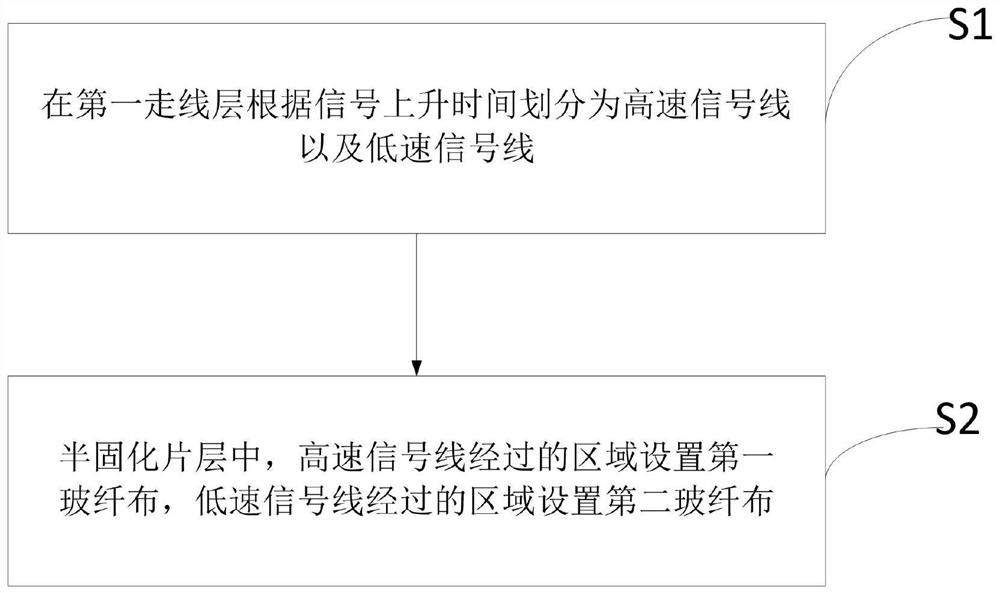
[0040] Such as image 3 As shown, the technical solution of the present invention also provides a method for splicing prepregs with glass fiber cloth in sub-regions, which is located between the first wiring layer and the second wiring layer adjacent to the first wiring layer, including:
[0041] S1, the first wiring layer is divided into high-speed signal lines and low-speed signal lines according to the signal rise time;
[0042]S2, in the prepreg layer, the first glass fiber cloth is set in the area where the high-speed signal line passes, and the second glass fiber cloth is set in the area where the low-speed signal line passes. The high-speed signal wiring path for communication connection of the wiring layer, the low-speed signal wiring path is the low-speed signal wiring path for communication connection with the second wiring layer through via holes in the first wiring layer, and the cost of the first glass fiber cloth is greater than that of the second glass fiber clo...
PUM
 Abstract
Description
Claims
Application Information
 - R&D
- Intellectual Property
- Life Sciences
- Materials
- Tech Scout
- Unparalleled Data Quality
- Higher Quality Content
- 60% Fewer Hallucinations
Browse by: Latest US Patents, China's latest patents, Technical Efficacy Thesaurus, Application Domain, Technology Topic, Popular Technical Reports.
© 2025 PatSnap. All rights reserved.Legal|Privacy policy|Modern Slavery Act Transparency Statement|Sitemap|About US| Contact US: help@patsnap.com


