Combine harvester

A combine harvester and frame technology, which is applied to harvesters, cutters, agricultural machinery and implements, etc., can solve the problems of high manufacturing cost and maintenance cost, reduce the service life of the whole machine, increase the chain length, etc., and reduce the manufacturing cost. and use and maintenance costs, reduce vibration and noise levels, and increase the effect of traction

Inactive Publication Date: 2011-08-17
夏发明
View PDF5 Cites 7 Cited by
  • Summary
  • Abstract
  • Description
  • Claims
  • Application Information

AI Technical Summary

Problems solved by technology

[0004] 1. The right stalk conveying and lifting chain of the header is too long, resulting in the length of the header itself being too long
[0005] 2. The position of the threshing drum is forced to be raised, so that the threshing method can only use the lower threshing method
[0006] 3. The engine drives the front wheels, which increases the wear on the track during the forward process and reduces the traction efficiency of the engine
[0007] 4. The vibration and noise of the console and the whole machine are too large, which reduces the service life of the whole machine and seriously affects the operator's operating experience
Under this structure, the ear head of the grain is drooping, which is inconsistent with the movement direction of the threshing nails on the threshing drum, so the ear head is easy to break
Most of the sundries are poured into the concave screen and piled up. The threshing system of the existing half-feed combine harvester is open, and most of the sundries are poured into the concave screen, which can easily cause blockage and cause a large number of The grains cannot pass through the concave plate sieve, but fall on the sundries and are discharged together with the sundries, resulting in food waste
And the flying sundries are easy to fly into the cleaning system, which will block the cleaning device and affect the cleaning work
It is very easy to cause blockage, causing a large amount of grains to fail to pass through the concave plate sieve, but to fall on the sundries and be discharged together with the sundries, resulting in food waste
And the flying sundries are easy to fly into the cleaning system, which will block the cleaning device and affect the cleaning work
[0009] 3. The cleaning system of the combine harvester on the existing market is mainly composed of a vibrating screen, a blower fan, a suction fan, a secondary horizontal auger, an inclined auger, and a grass discharge chain. The structure of the above-mentioned cleaning system is very complicated. Manufacturing and maintenance costs are high
And because the above-mentioned components are all installed under the threshing cylinder and the grass chain, it takes up a lot of space, so that the threshing cylinder has to be raised to a higher height.
The threshing drum is placed high, which raises the center of gravity of the whole machine, affects the stability of the whole machine, and increases the lifting height and difficulty of the header
And this kind of threshing method will bring problems such as easy to block the concave plate sieve, and the grain will be discharged together with the sundries to cause waste, etc.
[0010] 4. In terms of the structure design of the grass discharge chain of the existing combine harvester, since the drum is to the left, in order to avoid the stalks from being piled up on the unharvested crops when they are discharged directly, segmental conveying is adopted, but this method is easy to cause the grass discharge chain Unsmooth delivery at the connection, forming a blockage
[0011] Five, because the direction of motion of the grain-supporting dial teeth of the header of the existing combine harvester is perpendicular to the advancing direction of the harvester, it is difficult to play the role of grain-supporting for crops whose lodging direction is consistent with the motion direction of the grain-supporting dial fingers. Difficulty in harvesting crops

Method used


Image

  • Combine harvester
  • Combine harvester
  • Combine harvester

Examples


Embodiment 1

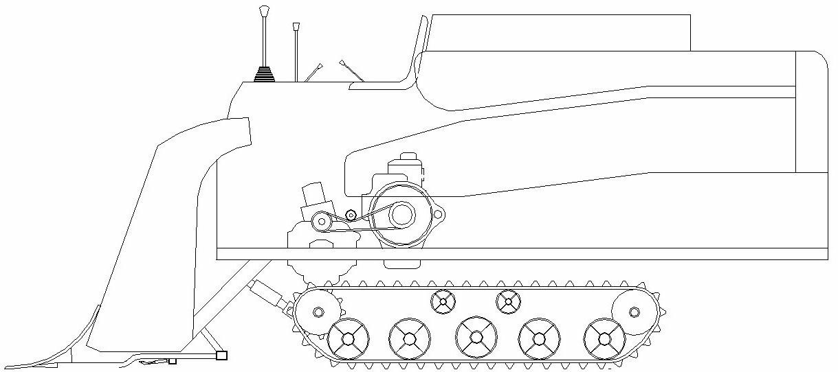
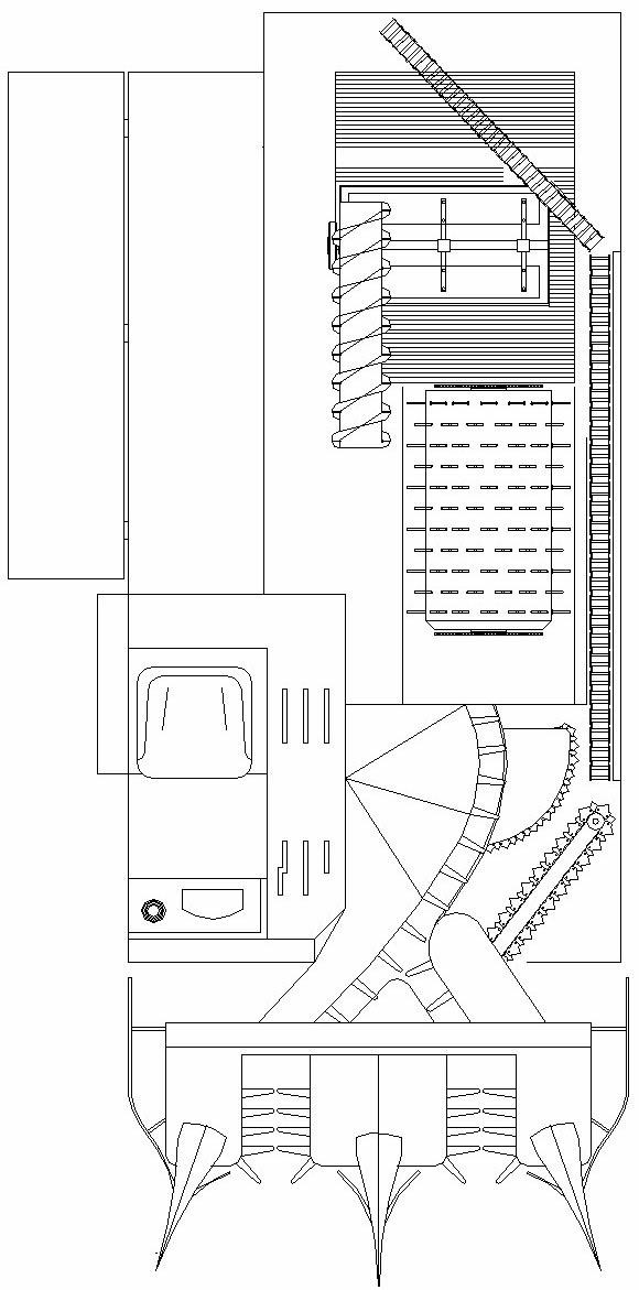
[0044] Such as image 3 and Figure 4 As shown, a combine harvester includes a header 1, an operating platform 2, a threshing system 3, a gearbox 4, an engine 5, a stalk conveyor chain 6, a frame 7, a traveling mechanism 8, and a secondary cleaning system 9; The frame 7 is fixedly installed on the running gear 8; the running gear 8 includes a front guide wheel 81, a rear driving wheel 82, rollers and crawlers; , gearbox 4 and engine 5 are fixedly installed on the frame 7, wherein, the engine 5 is installed in the rear of the complete machine, and is connected to the rear drive wheel 82 shafts in the running mechanism 8 through the gearbox 4; the threshing system 3 is between the two crawlers of the traveling mechanism, and the secondary cleaning system 9 is installed directly below the threshing system 3 .

[0045] Such as Figure 5 and Figure 6 As shown, the threshing system 3 includes a drum cover 31, a drum 32, a stalk conveying part 33 and a concave screen 34, the dru...

Embodiment 2

[0052] The distance between the lower end of the air deflector one 1 and the air deflector two 92 is 50mm. Other structures are the same as in Embodiment 1.

Embodiment 3

[0054] The distance between the lower end of wind deflector one 1 and wind deflector two 92 is 80mm. Other structures are the same as in Embodiment 1.


PUM


Abstract

The invention relates to an agricultural machine, in particular to a combine harvester. The combine harvester comprises a harvesting table, an operating table, a threshing system, a gear box, an engine, a stalks transmitting chain, a stander, a travelling mechanism and a second cleaning system; the stander is fixedly arranged on the travelling mechanism; the travelling mechanism comprises a front guide wheel, a back driving wheel, a thrust wheel and two crawler belts; the harvesting table, the operating table, the threshing system, the gear box and the engine are fixedly arranged on the stander, the engine is arranged behind a complete machine and connected with a back driving wheel shaft in the travelling mechanism by the gear box; and the threshing system is arranged between the two crawler belts of the travelling mechanism, and the second cleaning system is arranged under the threshing system. The combine harvester changes the structure of the traditional harvester, the structure is simpler and more reasonable, and the work efficiency can be greatly improved.

Description

technical field [0001] The invention relates to an agricultural machine, in particular to a combine harvester. Background technique [0002] Most of the structures of existing combine harvesters are as figure 1 and figure 2 As shown, its structure is not reasonable enough, and the following problems will occur. [0003] 1. The front of the engine is located under the console, so the position of the threshing drum must be set to the left of the whole machine, that is, above the left track. Such a structure brings about the following adverse effects. [0004] 1. The right stalk conveying and lifting chain of the header is too long, which causes the length of the header itself to be too long. [0005] 2. The position of the threshing drum is forced to be raised, so that the threshing method can only be the lower threshing method. [0006] 3. The engine drives the front wheels, which increases the wear on the track during the forward process and reduces the traction effici...

Claims


Application Information

Patent Timeline
Patent Type & Authority Applications(China)
IPC IPC(8): A01D41/02A01D41/06A01D41/12A01F12/18A01D57/22
Inventor 夏发明
Owner 夏发明
Why Eureka
Try Eureka