

Multi-fluid jet quench radial flow reactor
A flow reactor and multi-fluid technology, applied in chemical instruments and methods, chemical/physical processes, etc., can solve problems such as difficult to meet process requirements, difficult adjustment and operation, complex structure, etc., to achieve simple design, increased manufacturing difficulty, good mix effect
- Summary
- Abstract
- Description
- Claims
- Application Information
AI Technical Summary
Problems solved by technology
Method used
Image

Examples
Embodiment Construction
[0039] The present invention will be further described below in conjunction with the accompanying drawings and embodiments.
[0040] Such as figure 2 , 3 , 4, and 5.
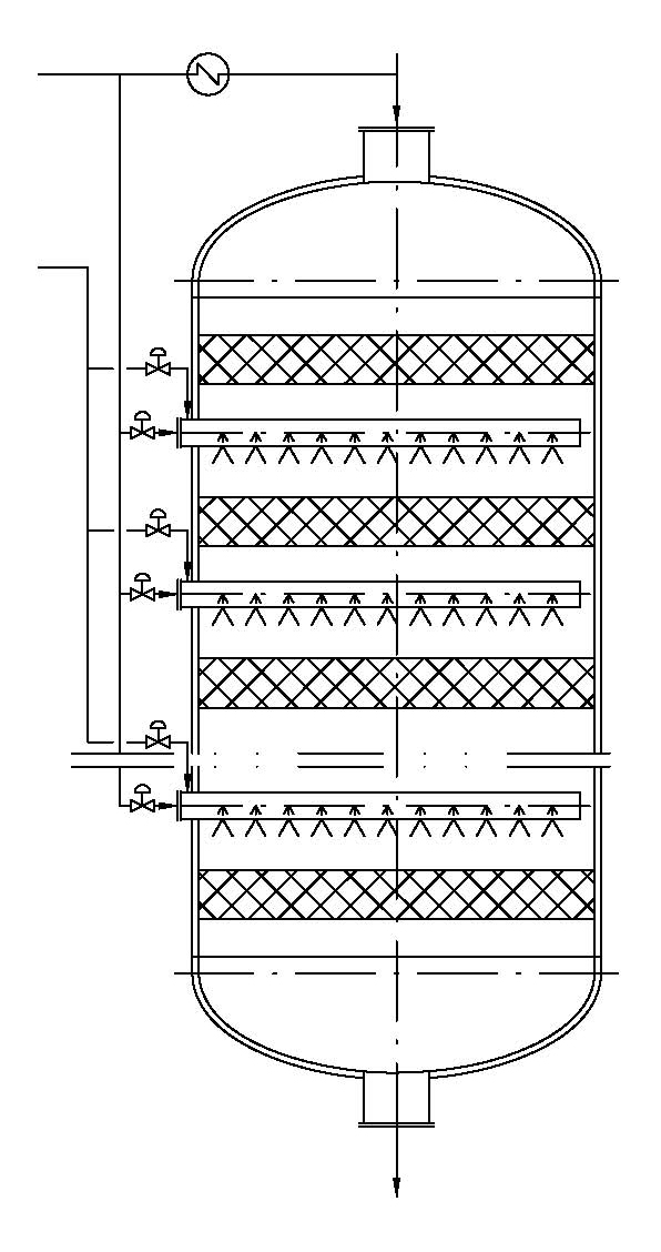
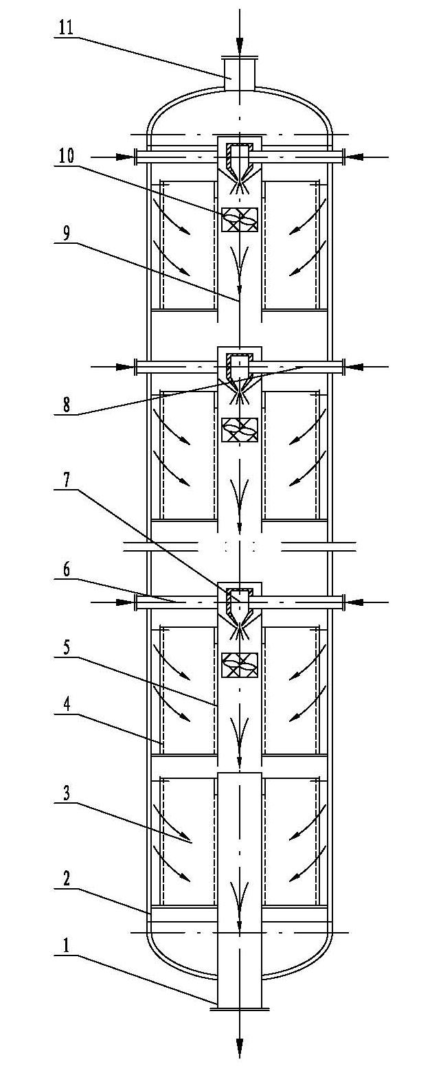
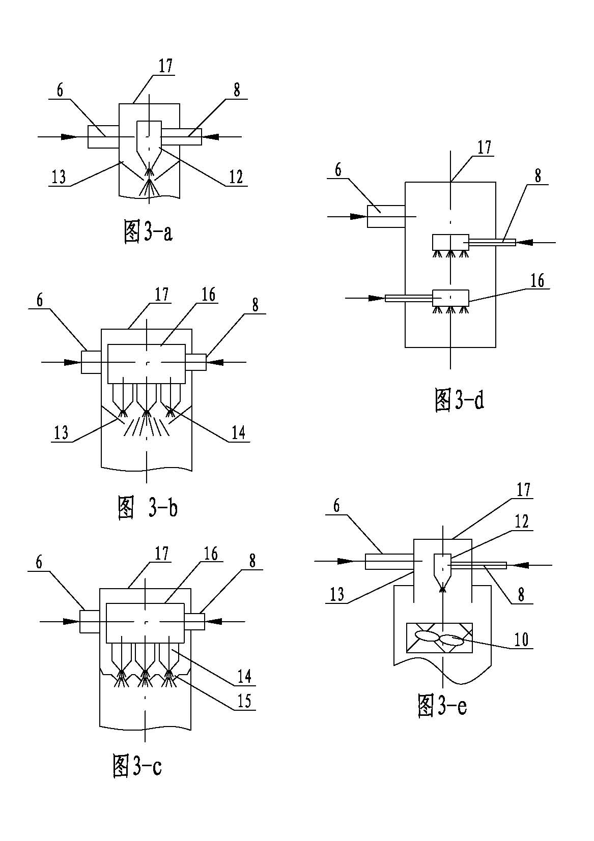
[0041]This example is a multi-fluid injection chilled radial flow reactor, which includes a radial reactor shell 2, the upper end of the shell 2 is provided with a gas inlet pipe 11 communicating with the inside, and the lower end of the shell 2 A gas outlet pipe 1 communicating with the inside is provided, and several radial catalytic beds 3 are provided in the housing 2, and each radial catalytic bed 3 is provided with a radial flow outer distribution cylinder 4, and the radial flow outer The center of the distribution cylinder 4 is provided with a radial flow inner gas collector 5, and a central mixing tube 9 is installed in the radial flow inner gas collector 5. Heat exchange can be performed between the radial flow inner gas collector 5 and the central mixing tube 9. The hot fluid in the gas collector 5...
PUM
 Abstract
Description
Claims
Application Information