Elastically-driven rotational joint

A technology of rotating joints and elastic drive, applied in the directions of manipulators, manufacturing tools, joints, etc., can solve the problems of complex mechanism, difficult installation and maintenance, small driving capacity, etc., and achieve the effect of broad application prospects, convenient installation and maintenance, and large output angle.

Inactive Publication Date: 2011-08-17
HARBIN ENG UNIV
View PDF5 Cites 28 Cited by
  • Summary
  • Abstract
  • Description
  • Claims
  • Application Information

AI Technical Summary

Problems solved by technology

This kind of driving method only has a one-way elastic buffering effect, and the stiffness of the elastic buffering element cannot be adjusted, and the overall size of the entire joint is relatively large
The third is to use the rope wheel transmission, and add a torsion spring device on the wheel shaft. This kind of driving method does not have self-locking, and the driving capacity is small, and the overall size of the joint is large.
The fourth is the disc circumferentially evenly distributed compression spring type elastically driven rotary joint. This method relies on the relative rotational movement of the inner and outer discs to compress the spring mechanism connected in series, thereby playing a buffering effect. This method does not have self-locking characteristics and the joint size is large , if there is vibration in the external load, the joint will vibrate accordingly, which will seriously affect the stability of the transmission
The fifth is to use the swing rod-pressure spring type adjustable elastic drive to rotate the joint. This driving method can realize the adjustable stiffness of the system, but the whole joint does not have self-locking characteristics, the overall mechanism is more complicated, and installation and maintenance are difficult.
[0004] In view of the above analysis, the volume of the existing elastically driven rotary joints is relatively large, which is not suitable for the application of micro-robots

Method used


Image

  • Elastically-driven rotational joint
  • Elastically-driven rotational joint
  • Elastically-driven rotational joint

Examples


Embodiment Construction

[0017] The present invention is described in more detail below in conjunction with accompanying drawing example:

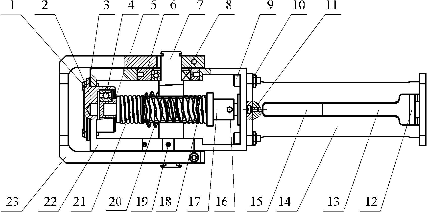
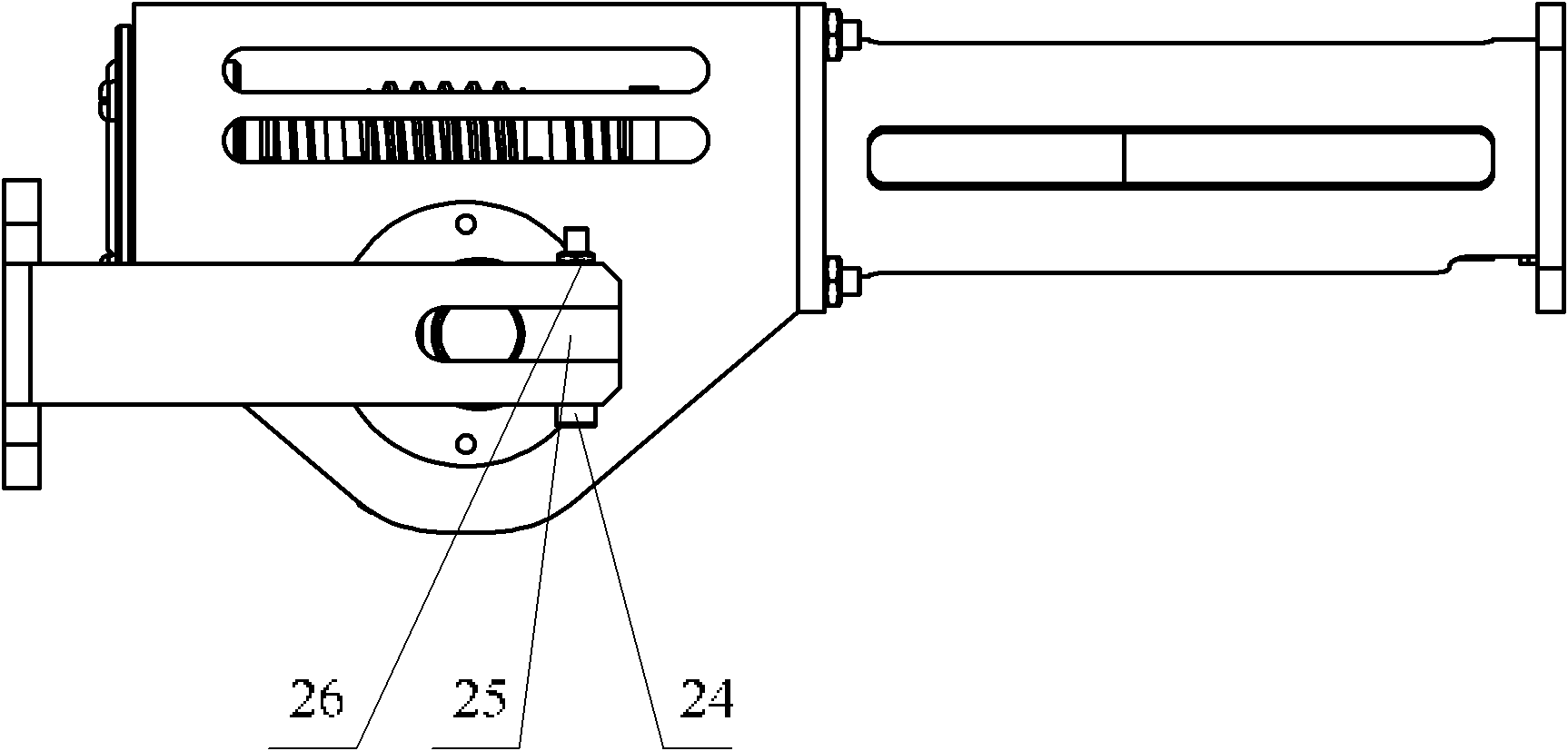
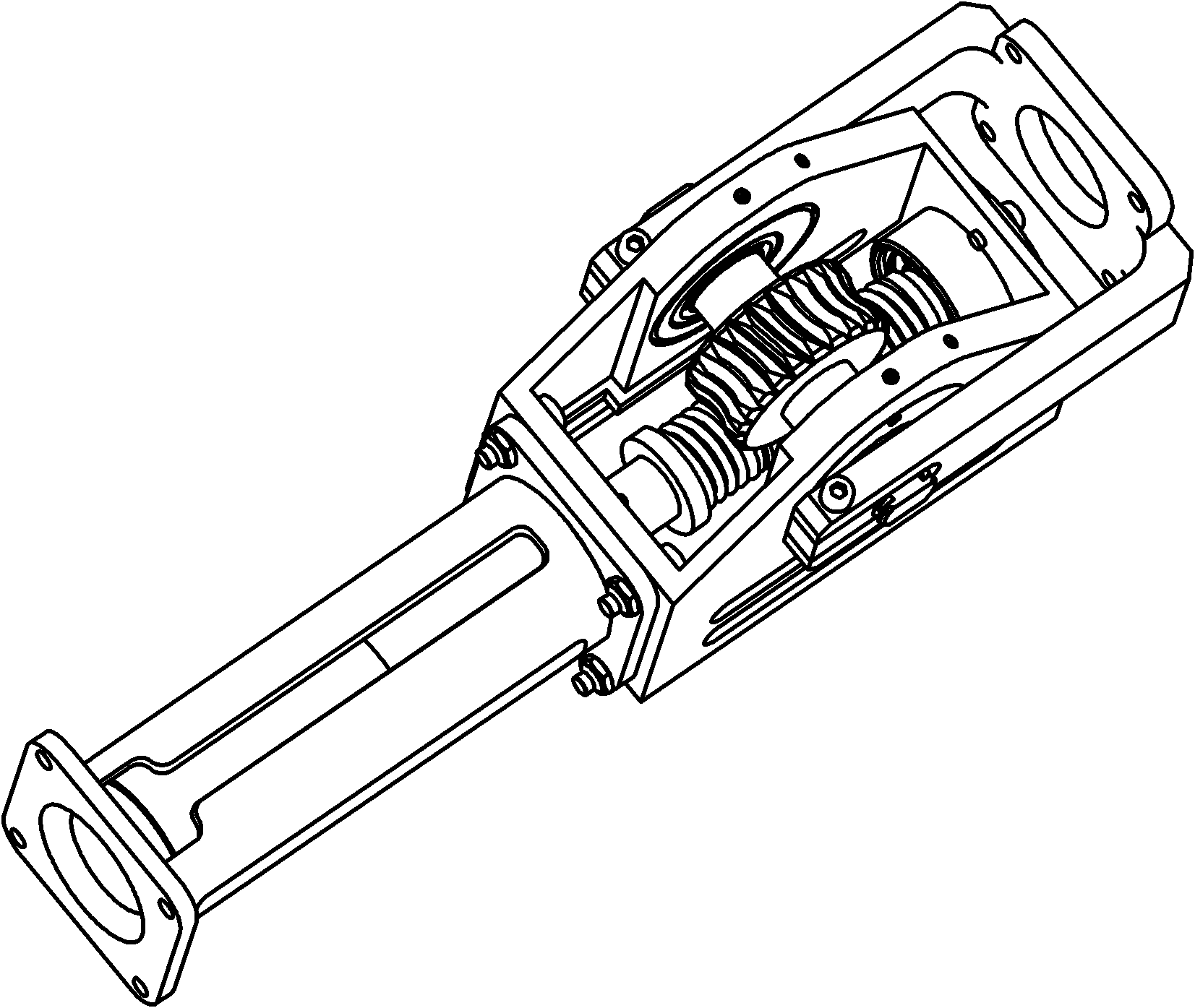
[0018] combine Figure 1 to Figure 3 , the elastically driven rotary joint of the present invention is mainly composed of the following parts: end cover screw 1, adjusting end cover 2, adjusting gasket 3, angular contact ball bearing 4, spring top sleeve 5, eccentric hole copper sleeve 6, worm gear 7 , deep groove ball bearing 8, hexagon socket bolt 9, nut 10, countersunk head screw 11, encoder 12, DC motor 13, motor frame 14, reduction box 15, cylindrical pin 16, spline shaft 17, first spring 18, Set screw 19, worm screw 20, second spring 21, box body 22, output frame 23, hexagon socket head bolt 24, U-shaped groove stopper 25, nut 26.

[0019] The specific implementation method of the present invention is as follows: the box body 22 and the motor frame 14 are connected by four hexagon socket bolts 9, which jointly constitute the supporting frame of the entire j...


PUM


Abstract

The invention aims at providing an elastically-driven rotational joint which comprises a motor frame, a box body, an output frame, a U-shaped slot check block, a coder, a direct current motor, a reduction box, a spline shaft, springs, a worm wheel, and a worm, wherein the box body is fixedly connected with the motor frame; the output frame is mounted on the box body through the U-shaped slot check block; the coder, the direct current motor, and the reduction box are arranged in the motor frame in sequence; the spline shaft is arranged in the box body; an output shaft of the reduction box is connected with the spline shaft; the springs also comprise a first spring and a second spring; the first spring, the worm, and the second spring are sheathed on the spline shaft in sequence; the worm wheel is arranged on the box body and is matched with the worm; and flat shaft ends at two ends of the worm wheel are matched with the U-shaped slot check block. The elastically-driven rotational joint has small size, large transmission ratio, self-locking, impact resistance, large output angle, strong commonality, and convenience for installation and maintenance. The elastically-driven rotational joint has broad application prospect in the field of microminiature bionic robots, in particular to occasions which require high appearance sizes on the robots and large transmission ratio, and exist rigid impact.

Description

technical field [0001] The invention relates to a joint with cushioning performance for a miniature bionic robot. Background technique [0002] With the development of the times, human beings' demand for robot applications continues to expand, especially in fields such as space exploration, seabed survey, nuclear energy industry, and emergency rescue, which place high requirements on the performance of robots. These environments are often unstructured unknown worlds not suitable for humans to reach. Therefore, the robot is required to have a strong ability to adapt to the environment. Taking this as a starting point, people put their research focus into the field of bionics, hoping to inspire design inspiration from animals in nature, and develop a robot system with high intelligence, good stability, and reasonable structure by imitating the movement and control mechanism of animals , and then can replace human beings to complete tasks in various dangerous, complex and unp...

Claims


Application Information

Patent Timeline
Patent Type & Authority Applications(China)
IPC IPC(8): B25J17/02
Inventor 王立权许俊伟陈东良王海龙常冬艳卿智忠
Owner HARBIN ENG UNIV
Why Eureka
Try Eureka