High-speed capping machine

A capping machine, high-speed technology, applied in the direction of flanged bottle caps, etc., can solve the problems of inadaptability to new requirements, difficulty in controlling the elasticity of the four-claw clip type, and difficulty in precise control of rolling knives, etc., to reduce the working surface Dead angle, protection of Class A cleanliness, stable and good workmanship

Inactive Publication Date: 2012-10-03
上海新旭发机械科技有限公司 +1
View PDF5 Cites 0 Cited by
  • Summary
  • Abstract
  • Description
  • Claims
  • Application Information

AI Technical Summary

Problems solved by technology

[0003] The three-rolling knife screwing and pressing type has the disadvantages of difficult adjustment of the rolling head and rolling knife for high-production multi-head capping machines, which is time-consuming and laborious, and requires debugging personnel to have a high technical level.
And this structure has a theoretical deadly debugging blind spot for vials of 2ml and below
Because the rolling angle and position of the rolling knife are not easy to control accurately, it is easy to cause broken bottles
[0004] The four-jaw clip type is not easy to control accurately due to its elasticity, and there are also shortcomings in the structural manufacturing process for high-speed capping.
[0005] Although the structure of the multi-head eccentric large plate single rolling knife is simple and easy to adjust, and the manufacturing cost is low, but this structure also correspondingly increases the requirements for glass bottles, rubber stoppers and aluminum-plastic caps
In actual production, it is difficult to make higher requirements on bottles, stoppers and caps based on the fixed and unique benchmark of large pan knives
Due to reasons such as manufacturing and assembly, a single large plate rolling knife will have a linkage effect on vials in different rolling stages during the rolling process, which will affect the uniform sealing effect of capping
[0006] The promulgation and implementation of the new version of GMP, as well as the increase in the output of other equipment in the washing, drying, filling and freezing rolling production line, have put forward higher requirements for the capping process. Failure to adapt to new requirements

Method used


Image

  • High-speed capping machine
  • High-speed capping machine
  • High-speed capping machine

Examples


Embodiment Construction

[0022] The present invention will be described in detail below in conjunction with the examples.

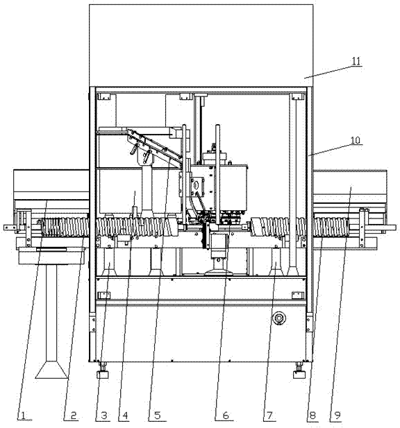
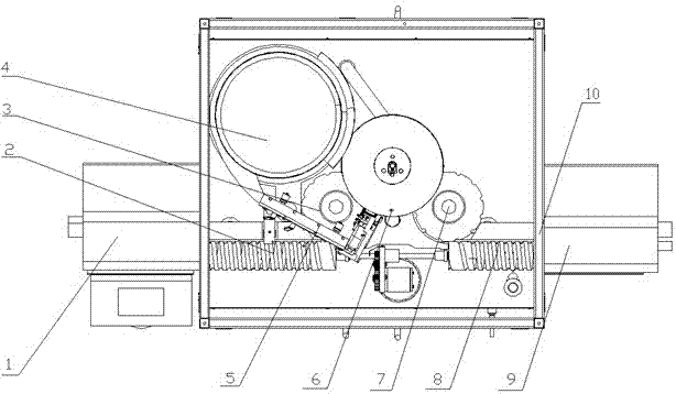
[0023] like figure 1 and figure 2 As shown, a high-speed capping machine provided by the present invention includes a shield 10, a laminar flow shield 11 is arranged above the shield 10, and a bottle inlet station 1 and a bottle outlet are respectively arranged on both sides of the shield 10. Station 9, the oscillating type aluminum cover feeding device 4 is arranged in the shield 10, the aluminum cover chute 5 inclined downward is provided at the outlet of the oscillating type feeding device 4, and the aluminum cover chute 5 is provided below The bottle feeding tray 3, one end of the bottle feeding screw 2 is set beside the bottle feeding tray 3, and the other end is set next to the bottle feeding station 1, and the vials in the bottle feeding station 1 are sent to the bottle feeding via the bottle feeding screw 2 On the plate 3, the aluminum cap enters the aluminum cap chute...


PUM


Abstract

The invention provides a high-speed capping machine which is characterized by comprising a protective cover, wherein the two sides of the protective cover are provided with a bottle inlet station and a bottle outlet station respectively; an oscillation type aluminum cover feed device is arranged in the protective cover; a downward-oblique aluminum cover chute is arranged at the outlet of the oscillation type feed device; a bottle feed plate is arranged below the aluminum cover chute; one end of a bottle inlet screw is arranged beside the bottle inlet plate, and the other end is arranged beside the bottle inlet station; one end of a bottle outlet screw is arranged beside the bottle outlet station, and the other end is arranged beside a bottle outlet plate in the protective cover; and a rotary capping device with at least 12 rolling heads and 12 built-in single blades is arranged between the bottle inlet plate and the bottle outlet plate. The high-speed capping machine provided by the invention has the advantage that the single-machine output meets the current and future requirements for the speed of the washing, baking, pouring, freezing and rolling production line, and conforms tothe new specification.

Description

technical field [0001] The invention relates to a capping machine, which is used in the capping and sealing process of aluminum caps or aluminum-plastic composite caps in glass bottle powder injections, freeze-dried powder injections and water injection pharmaceutical manufacturers. Background technique [0002] In the pharmaceutical equipment market, the early single-head manual capping machine had a low speed and could only reach 60 bottles / min. Since the end of the 1980s, capping machines with various structures have appeared one after another. Among them, the representative ones are the three-knife screwing and pressing type, the four-jaw clamping type and the multi-head eccentric large-plate single-knife structure. The speed is also increased to about 200-300 bottles / min. Through the use of my country's pharmaceutical manufacturers for many years, it is reflected that there are different defects. [0003] The three-knife screwing and pressing type has the disadvantag...

Claims


Application Information

Patent Timeline
Patent Type & Authority Patents(China)
IPC IPC(8): B67B3/02
Inventor 魏国琴
Owner 上海新旭发机械科技有限公司
Why Eureka
Try Eureka