Waterproof method for precast pile head

A technology of prefabricated pile heads and prefabricated piles, which is applied in the direction of protection devices, buildings, and infrastructure engineering, etc., can solve the problems that are not easy to do, and the flexible waterproof layer is difficult to achieve reliable waterproofing, so as to achieve the effect of improving the reliability of waterproofing

Inactive Publication Date: 2011-08-17
吴兆圣
View PDF3 Cites 18 Cited by
  • Summary
  • Abstract
  • Description
  • Claims
  • Application Information

AI Technical Summary

Problems solved by technology

[0002] According to the provisions of GB50108-2009 "Technical Specifications for Waterproofing of Underground Engineering", the design, materials and process of pile head waterproofing have a direct and important impact on the success or failure of underground engineering waterproofing. Due to the influence of existing technologies, materials and other factors, in A flexible outsourcing waterproof layer is provided on the facing surface of the bottom plate. To achieve reliable waterproofing, it is definitely not easy to do
This is because the cap and the cushion are post-cast, and there is a construction joint between the pile cap, the cap and the cushion, and the pressurized groundwater will enter the basement through the construction joint between the cushion and the steel pipe wall of the pile head. The surface of the bottom plate, so the flexible waterproof layer set on the water-facing surface of the bottom plate is difficult to achieve reliable waterproofing

Method used


Image

  • Waterproof method for precast pile head
  • Waterproof method for precast pile head

Examples


Embodiment Construction

[0011] The specific embodiments of the present invention will be described in detail below with reference to the accompanying drawings.

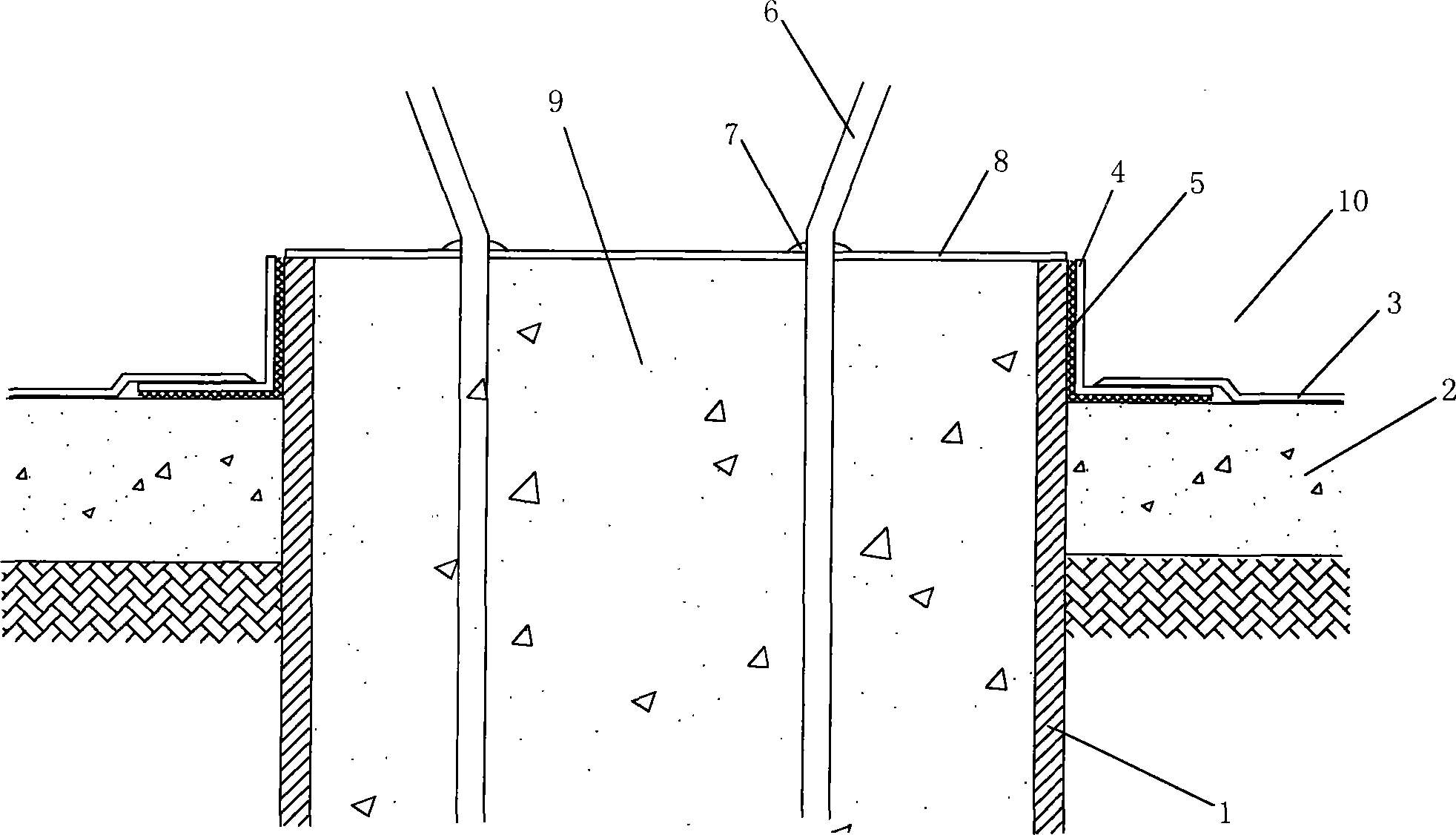
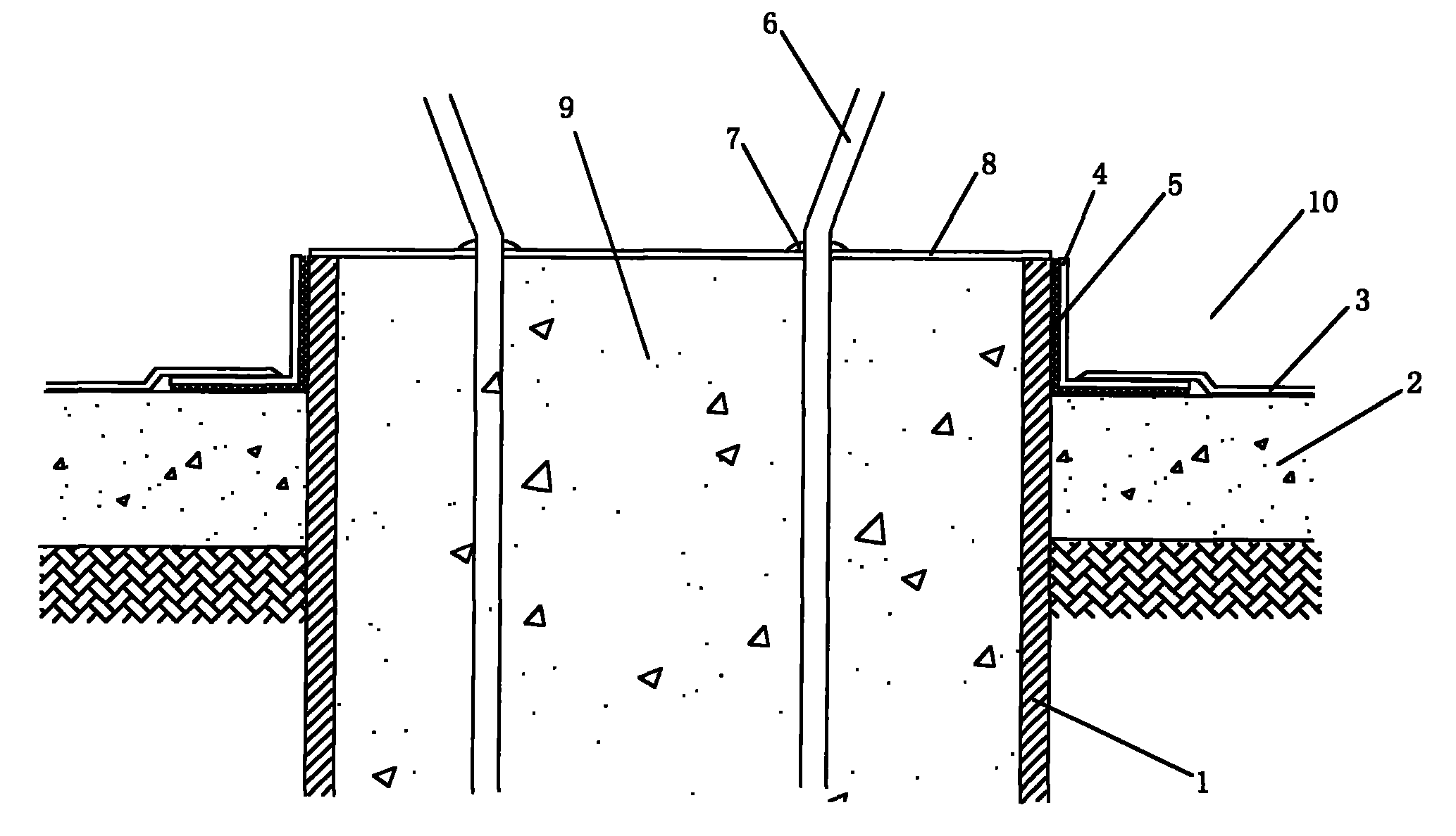
[0012] Precast piles generally include steel pipe piles and precast reinforced concrete piles, such as figure 1 Shown is a steel pipe pile, and the outer wall 1 of the pile head is a steel pipe; for a prefabricated reinforced concrete pile, the outer wall is concrete.

[0013] The waterproof method of the present invention, such as figure 1 Shown is the pile head section structure diagram of the steel pipe pile, including the steps:

[0014] Put the pile head waterstop 4 into the pile head; the pile head waterstop 4 is a cylindrical casing, which can be inserted into the pile head. The periphery of the pile head is generally cylindrical, and the inside is poured with concrete 9 and connecting steel bars 6;

[0015] Break open the inner ring of the pile head waterstop 4, inject epoxy resin adhesive 5, bond one wing of the pile head watersto...


PUM


Abstract

The invention discloses a waterproof method for a precast pile head. The method comprises the following steps of: sheathing a pile head water stopper into the pile head; opening the inner ring of the pile head water stopper, injecting epoxy resin adhesive into the inner ring, sticking one wing of the pile head water stopper to the outer wall of the pile head, and sticking the other wing of the pile head water stopper to the pad layer of a bottom plate; and spreading a bottom plate waterproof coiled material on the pad layer of the bottom plate, and welding or sticking the other wing of the pile head water stopper to the bottom plate waterproof coiled material. In the waterproof method, one wing of the pile head water stopper is stuck to the outer wall of the pile head steel pipe, the other wing of the pile head water stopper is stuck to the pad layer of the pile head, and the other wing of the pile head water stopper is welded or stuck to the bottom plate waterproof coiled material spread on the pad layer, so that a waterproof layer of the pile head and the bottom plate waterproof coiled material are seamlessly connected, the underground water is prevented from entering the surface of a basement bottom plate through a construction seam between the bottom plate and the outer wall of the pile head, and the waterproof reliability is improved.

Description

technical field [0001] The invention relates to building waterproofing, in particular to a waterproofing method for prefabricated pile heads. Background technique [0002] According to GB50108-2009 "Technical Specifications for Underground Engineering Waterproofing", the design, material and process of pile head waterproofing have a direct and important impact on the success or failure of underground engineering waterproofing. A flexible outer waterproof layer is set on the water-facing surface of the bottom plate, and it is definitely not easy to achieve reliable waterproofing. This is because the cap and the cushion are post-cast, and there is a construction joint between the pile head, the cap and the cushion, and the groundwater under pressure will enter the basement through the construction joint between the cushion and the wall of the steel pipe at the pile head. The surface of the bottom plate, so the flexible waterproof layer arranged on the upstream surface of the ...

Claims


Application Information

Patent Timeline
IPC IPC(8): E02D31/02
Inventor 吴兆圣张道真
Owner 吴兆圣
Why Eureka
Try Eureka