Combined clamp for rack upright post pressure test

A pressure test and shelf column technology, applied in the direction of measuring devices, instruments, scientific instruments, etc., can solve the problems of inaccurate description of column performance, different end structures or sizes, column test pieces cannot be hinged, etc., to reduce work intensity , Improve efficiency and improve utilization

Inactive Publication Date: 2011-08-17
DONGHUA UNIV
View PDF3 Cites 3 Cited by
  • Summary
  • Abstract
  • Description
  • Claims
  • Application Information

AI Technical Summary

Problems solved by technology

However, how to accurately and conveniently complete the shelf column pressure test still has the following problems: (1) The two ends of the column test piece cannot be completely hinged with the upper and lower workbenches of the press, and a set of special fixtures needs to be designed; (2) At present , the simplified method is mostly used in engineering
Therefore, the test is not a complete column axial compression test, which makes the test process and the test principle different, and the test results cannot accurately explain the performance of the column; (3) Different types of column test pieces have different end structures or sizes , for different fixtures designed for different specimens, it will greatly increase the test cost

Method used


Image

  • Combined clamp for rack upright post pressure test
  • Combined clamp for rack upright post pressure test
  • Combined clamp for rack upright post pressure test

Examples


Embodiment 1

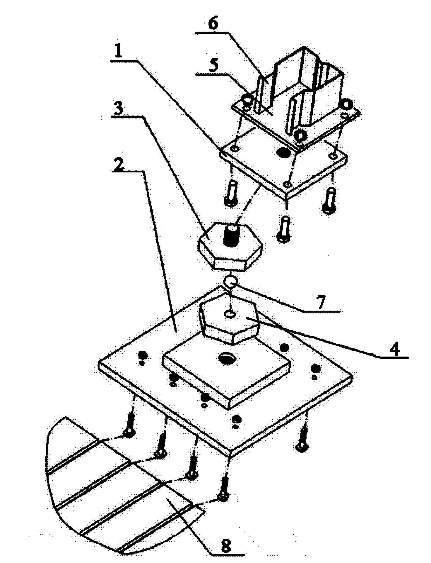
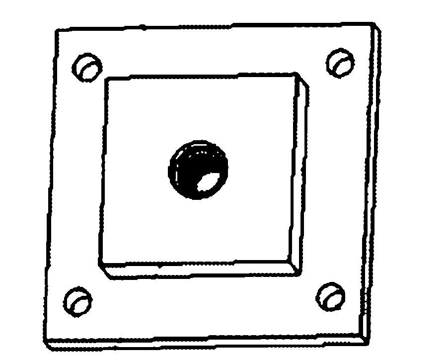
[0022] Embodiment 1: This embodiment relates to a combination fixture used for a shelf column pressure test, such as figure 1 As shown, the column fixing plate 1 is connected with the column bottom plate 5 welded with the column 6 by 4 hex bolts through the bolt holes on the 4 column fixing plates 1 . Such as figure 2 , image 3 with Figure 4 As shown, the middle part of one side of the upper steel ball clamping block 3 has a threaded column, and the middle part of the other side is provided with a spherical groove. The middle part of the boss of the column fixing plate 1 has a threaded hole that runs through the whole. Align the threaded hole in the center of the column fixing plate 1 and screw it in to fix it. The workbench fixing plate 2 is placed on the T-slot workbench 8 of the press, and fixed on the T-slot workbench 8 through the 8 bolt holes on the workbench fixation plate 2 with 8 T-bolts. The bolt can move along the T-shaped slot to adjust the position of the w...

Embodiment 2

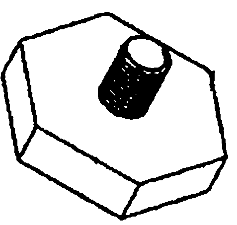
[0023] Embodiment 2: This embodiment also relates to a combination fixture used for a shelf column pressure test, its structure is roughly the same as that of Embodiment 1, the difference is that, as Image 6 with Figure 7 As shown, the structure of the upper and lower steel ball clamping blocks in this embodiment is that the middle part of one side is provided with threaded columns, and the middle part of the other side is provided with bosses, and the bosses of the upper and lower steel ball clamping blocks are all provided with threaded columns. Features spherical grooves. By adding a boss on one side of the steel ball clamping block, the fixture can be applied to steel balls with a smaller diameter, thereby avoiding collisions when the steel ball clamping block rotates around the steel ball. The method of installing the steel ball clamp described in Embodiment 1 is also applicable to the method of installing the steel ball clamp in this embodiment. When replacing the st...


PUM


Abstract

The invention relates to a combined clamp for a rack upright post pressure test. The combined clamp comprises an upright post fixing plate, a worktable fixing plate, an upper steel ball clamping block and a lower steel ball clamping block, wherein an upright post bottom plate is fixed on the upper surface of the upright post fixing plate; an upright post is welded on the upright post bottom plate; the lower surface of the upright post fixing plate is connected with the upper steel ball clamping block; a T-shaped groove worktable is fixed on two sides of the worktable fixing plate respectively; the upper surface of the worktable fixing plate is connected with the lower steel ball clamping block; and the same groove for clamping steel balls is formed between opposite surfaces of the upper steel ball clamping block and the lower steel ball clamping block. The combined clamp can guarantee that two ends of a test piece are always hinged with a press worktable in the test, and the test result is more accurate.

Description

technical field [0001] The invention relates to a fixture, in particular to a combined fixture used for the pressure test of a shelf column. Background technique [0002] In engineering practice, there are a large number of shelf columns that need to be pressure tested. The principle of the shelf column test is given in (EU logistics equipment standard FEM10.2.02-shelf design specification). Fully articulated. However, how to accurately and conveniently complete the shelf column pressure test still has the following problems: (1) The two ends of the column test piece cannot be completely hinged with the upper and lower worktables of the press, and a set of special fixtures needs to be designed; (2) At present , the simplified method is mostly used in engineering. That is, no hinge or the upper end is hinged and the lower end is not hinged. Therefore, the test is not a complete column axial compression test, which makes the test process and the test principle different, an...

Claims


Application Information

Patent Timeline
Patent Type & Authority Applications(China)
IPC IPC(8): G01N3/04
Inventor 杨建国吕志军姚道壮
Owner DONGHUA UNIV
Why Eureka
Try Eureka