Printing machine

A technology for printing presses and printing rollers, applied in printing presses, rotary printing presses, printing, etc., can solve the problems of inability to shorten the length of the film, waste, and long materials.

Active Publication Date: 2017-12-01
FOSHAN PUYING MACHINERY EQUIP
View PDF13 Cites 2 Cited by
  • Summary
  • Abstract
  • Description
  • Claims
  • Application Information

AI Technical Summary

Problems solved by technology

Traditional printing machines adopt the form of placing the printing machine and embossing machine horizontally. Due to the limitation of the volume of the embossing machine, this form cannot shorten the length of the film between the printing machine and the embossing machine, resulting in film deformation and inability to Problems aligning printed and embossed patterns
[0004] In the existing film embossing devices, a single motor is used to drive the embossing roller to rotate, and the rubber roller is passively operated to realize the embossing of the film. The biggest disadvantage of this design is that if the printing pattern and the embossing roller If the lines do not match, when it needs to be adjusted, it is necessary to speed up or slow down the printing speed of the printing roller, and there is a long distance between the printing roller and the embossing roller. To make the speeds of the two consistent, adjust During the period, a very long amount of material needs to be wasted, and it needs to be adjusted to be completely consistent, requiring multiple trials to meet the requirements
In addition, since this design adjusts the printing speed according to the embossing speed, the film basically pulls the film forward through the rotation of the embossing roller, and the length of the film between the embossing roller and the printing roller is longer, and the film The tensile force is relatively large, and the film will be deformed by the tension during this process, making it more difficult to achieve the correspondence between the printed pattern and the embossed pattern

Method used


Image

  • Printing machine
  • Printing machine
  • Printing machine

Examples


Embodiment 1

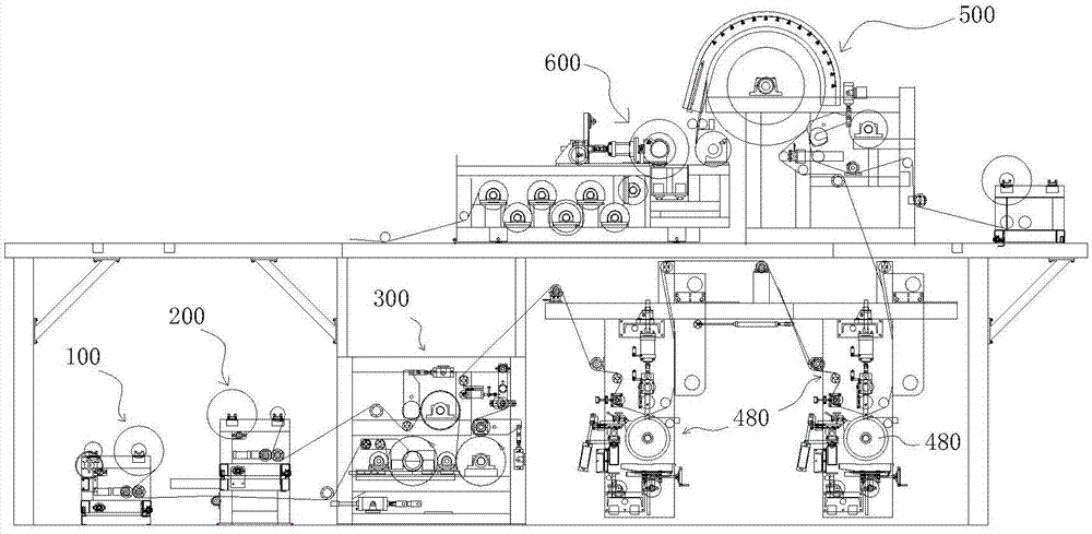
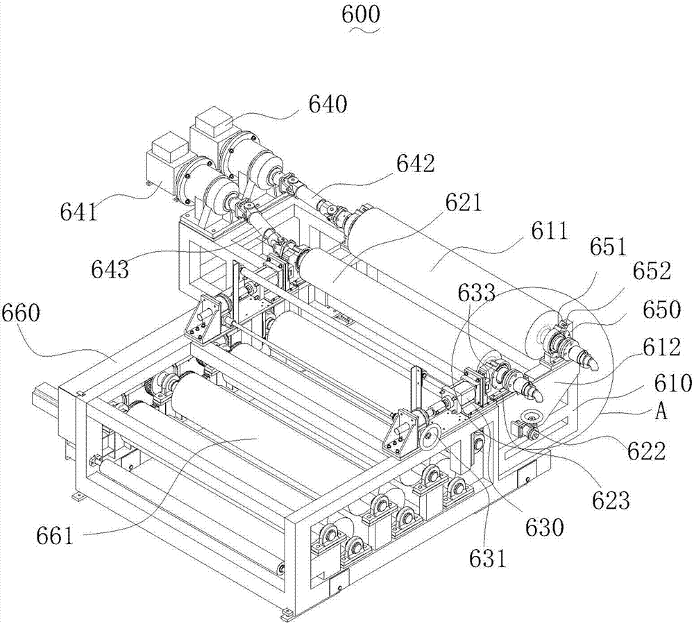
[0037] Such as Figure 1-5 As shown, a printing machine in this embodiment includes a printing assembly 400 and an embossing assembly 600. The printing assembly 400 includes several printing rollers 480, and the film enters the embossing assembly 600 after printing on the printing rollers 480. The embossing assembly 600 is arranged above the printing assembly 400, and the length of the film between the last printing cylinder 480 and the embossing assembly 600 is less than or equal to twice the length of the film between two adjacent printing cylinders 480; The embossing assembly 600 described above includes a first support 610, a rubber roller 611 arranged on the first support 610, a second support 620, and an embossing roller 621 arranged on the second support 620. The surface of the embossing roller 621 is It is provided with the same uneven texture as the film pattern, the rubber roller 611 and the embossing roller 621 are respectively connected to the first motor 640 and t...

Embodiment 2

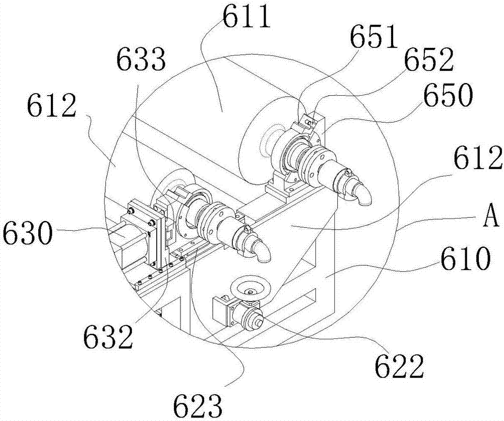
[0039] Such as Figure 1-5 As shown, the rubber roller 611 is connected to the first motor 640 through the first universal coupling 642, and the embossing roller 621 is connected to the second motor 641 through the second universal coupling 643. The rubber roller 611 is fixed on the first bracket 610 through the fixed seat 650, the embossing roller 621 is arranged on the second bracket 620, and the first bracket 610 is provided with a left and right moving slide rail 613, and the described The second bracket 620 is connected to the first bracket 610 through the left and right moving slide rails 613 , and the first bracket 610 can slide on the left and right moving slide rails 613 to adjust the left and right relative positions of the embossing roller 621 and the rubber roller 611 . The first bracket 610 is provided with a support plate 612, the support plate 612 is provided with a left and right position regulator 622, and the left and right position regulator 622 is connected...

Embodiment 3

[0041] Such as figure 1 , 6 , 7, 8, 9, and 10, the printing assembly includes a fixed frame 410, a printing cylinder 480 arranged on the fixed frame 410, a scraper 472 is also arranged on the fixed frame 410, and the scraper 472 is arranged on On the movable plate 470 , the scraper 472 contacts or separates from the printing cylinder 480 under the action of the movable plate 470 . The fixed frame 410 is also provided with an adjustment plate 411, a support member 420 and a longitudinal movement plate 440, the movable plate 470 is arranged on the longitudinal movement plate 440, the support member 420 is provided with a longitudinal movement slide rail 421, and the adjustment plate 411 An adjuster 430 is provided, and the adjuster 430 is connected with the longitudinally moving plate 440 and controls the longitudinally moving plate 440 to move longitudinally on the longitudinally moving slide rail 421, and a support frame 450 is also provided, and the movable plate 470 is arra...


PUM


Abstract

The invention relates to a printing machine. The printing machine comprises a printing assembly and an embossing assembly. The printing assembly comprises a plurality of printing rollers, and a film enters the embossing assembly after being printed by the printing rollers. The embossing assembly is arranged above the printing assembly. According to the printing machine, the embossing assembly is arranged over the printing rollers or above the printing rollers, so that the traditional mode of placing the embossing assembly and the printing rollers in parallel is changed, he length of the portion, between the embossing assembly and the printing rollers, of the film is shortened, the influence that the film is deformed due to tension action is reduced, a printing pattern can be accurately aligned to an embossing pattern, and the product quality is improved.

Description

【Technical field】 [0001] This invention relates to printing machines. 【Background technique】 [0002] Composite film is a polymer material composed of two or more layers of films of different materials. Because of its characteristics that single-layer films do not have, it is more and more popular and used more and more in daily life. Therefore, Laminating single-layer films with different properties is an indispensable part of the composite film production process. The lamination of the film often requires heating the film, and the traditional lamination device will inevitably generate air bubbles during the preheating process, which will affect the quality of the composite film. In addition, different films need to be heated at different temperatures. If the temperature is too high, the film may be deformed and affect the bonding effect. If the film is in a suspended state after heating, the temperature of the film will be taken away because the air temperature is lower ...

Claims


Application Information

Patent Timeline
Patent Type & Authority Applications(China)
IPC IPC(8): B41F19/06
CPCB41F19/062
Inventor 龚卫坚陈冠棣
Owner FOSHAN PUYING MACHINERY EQUIP
Why Eureka
Try Eureka