Lightning surge generator

A surge generator and surge technology, applied in the field of research and testing, can solve problems such as complex operation, increased cost of test equipment, and slow test speed

Active Publication Date: 2011-08-17
远方谱色科技有限公司
View PDF4 Cites 16 Cited by
  • Summary
  • Abstract
  • Description
  • Claims
  • Application Information

AI Technical Summary

Problems solved by technology

[0003] At present, the main equipment for testing and researching the anti-lightning surge ability of electronic equipment is the lightning surge generator, which usually needs to be equipped with expensive voltage and current probes and oscilloscopes to realize the analysis and display of surge voltage and current waveforms. This combination method not only increases the cost of the test equipment, but also complicates the operation and lowers the safety
In addition, the general method for lightning surge generators to test the anti-surge capability of electronic equipment is to apply different levels of surges to the electronic equipment to test the anti-surge level of the equipment under test. This method is slow in testing speed and cannot accurately find The breakdown voltage of electronic equipment, which can also cause significant damage due to excessively large applied surges

Method used


Image

  • Lightning surge generator
  • Lightning surge generator
  • Lightning surge generator

Examples


Embodiment 1

[0015] The following examples further describe the present invention.

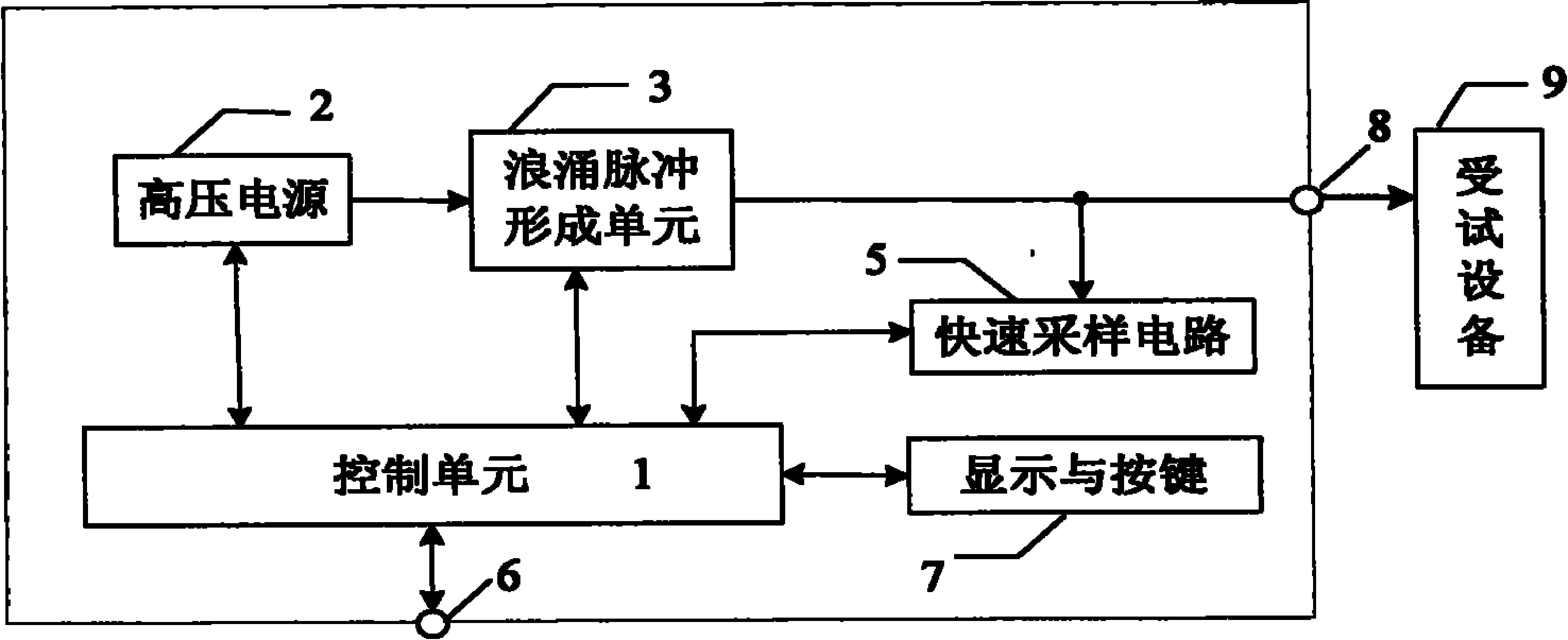
[0016] Such as figure 1 As shown, a structural block diagram of a lightning surge generator includes a high-voltage power supply 2, a surge pulse forming unit 3, a control unit 1, a fast sampling circuit 5, a synchronous trigger port 6, a display and a button 7. The output terminal of the high-voltage power supply 2 is connected with the input terminal of the surge pulse forming unit 3. The surge pulse forming unit 3 outputs the generated surge through the test terminal 8 of the equipment under test, and the synchronous fast sampling circuit 5 sets the sampling point in the surge pulse formation Between unit 3 and test terminal 8 of the equipment under test.

[0017] In this embodiment, the high-voltage power supply 2 is a DC high-voltage source, and the control unit 1 controls the high-voltage power supply 2 to sequentially output DC voltages in a certain step length, so that the surge pulse forming unit 3 als...

Embodiment 2

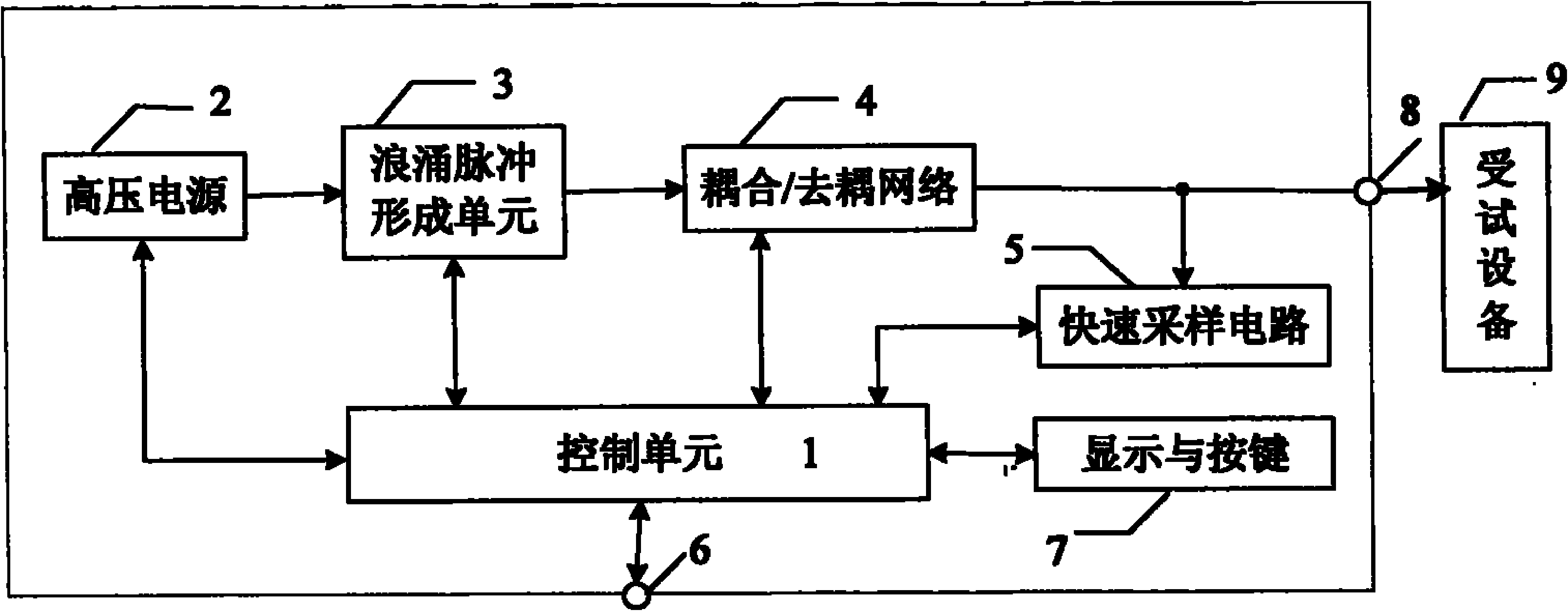
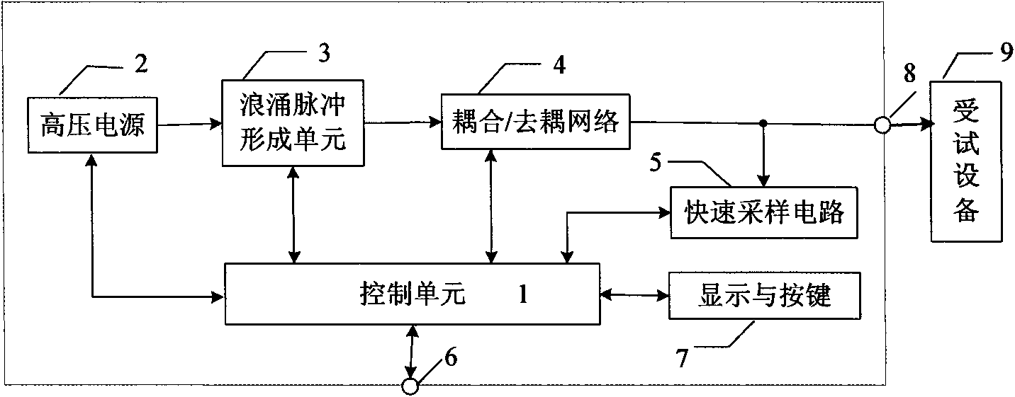
[0022] Such as figure 2 As shown, a structural block diagram of a lightning surge generator is shown. The lightning surge generator of this embodiment is similar to the first embodiment. The main test is that when the device under test is connected to the power grid, in addition to the components described in Example 1, the lightning surge generator also includes a coupling / decoupling network 4, which is mainly used to generate the surge pulse forming unit 3 The pulse is coupled to the equipment under test and decoupling with the power grid is formed to prevent the surge pulse from interfering with the public power grid.

[0023] In this embodiment, the control unit 1 controls the high-voltage power supply 2 to sequentially output DC voltages in a certain step length, so that the surge pulse forming unit 3 also sequentially outputs surge pulses in a certain step length, and the generated surge pulses are coupled / decoupled The network 4 is coupled to the test terminal 8 of the e...


PUM


Abstract

The invention discloses a lightning surge generator. By arranging a quick sampling circuit for synchronously acquiring voltage and current waveform data of surge pulse in an instrument, the test data can be intuitively and quickly analyzed, integration of test and analysis is realized, the operation is more convenient, and meanwhile, the cost of a test instrument is reduced. By intelligently designing a control unit, the tested voltage and current waveform data are compared with the limit value of the tested equipment to automatically screen unmatched products, so the test efficiency is greatly improved. The control unit can also control sequential increment of the surge pulse according to a certain step length, so that the surge resistant level of the tested equipment can be accurately positioned, a minimum breakdown voltage can be found, great damage to the tested equipment can also be avoided, and the safety is higher.

Description

【Technical Field】 [0001] The invention belongs to the field of electromagnetic compatibility (EMC) testing, in particular to the research and testing of the surge resistance capability of the equipment under test (EUT). 【Background technique】 [0002] During the use of electronic and electrical equipment, surges caused by equipment switching, electrostatic discharge, circuit failure, lightning strikes, etc. will cause certain damage to electronic equipment. Among them, lightning strikes are the most destructive to electronic equipment. Therefore, the test of electronic equipment The ability to resist lightning surges is an important factor in evaluating the performance of its products. The national standard GB / T 17626.5: 2008 and the international standard IEC 61000-4-5: 2005 have made strict regulations on the test of the anti-surge ability of electronic equipment, including the test equipment, surge voltage, current waveform, etc. Clear requirements. [0003] At present, the ma...

Claims


Application Information

Patent Timeline
Patent Type & Authority Applications(China)
IPC IPC(8): G01R31/12
Inventor 季军潘建根涂辛雅胡月霞
Owner 远方谱色科技有限公司
Why Eureka
Try Eureka