Chip for imaging box

An imaging box chip and imaging box technology, applied in electrography, optics, printing, etc., can solve problems such as cumbersome process, achieve the effect of simplifying the operation process and improving work efficiency

Inactive Publication Date: 2011-08-17
APEX MICROELECTRONICS CO LTD
View PDF3 Cites 2 Cited by
  • Summary
  • Abstract
  • Description
  • Claims
  • Application Information

AI Technical Summary

Problems solved by technology

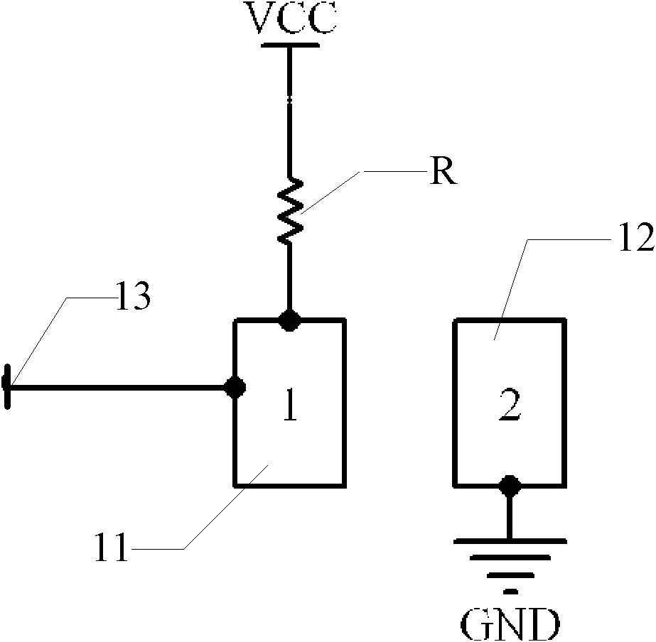
[0007] It can be seen from this that in the prior art, in the recognition process of the printer after injecting new colorant, no matter what kind of printer it is, it is necessary to perform the operation of taking out and putting into the imaging cartridge after injecting the colorant every time. It is very cumbersome for the printer to determine and read the value in the chip of the imaging cartridge after reset, and then continue to work

Method used


Image

  • Chip for imaging box
  • Chip for imaging box
  • Chip for imaging box

Examples


Embodiment Construction

[0056] The following will clearly and completely describe the technical solutions in the embodiments of the present invention with reference to the accompanying drawings in the embodiments of the present invention. Obviously, the described embodiments are only some, not all, embodiments of the present invention. Based on the embodiments of the present invention, all other embodiments obtained by persons of ordinary skill in the art without making creative efforts belong to the protection scope of the present invention.

[0057] The invention discloses an imaging box chip, the structure of which is as follows: Figure 4 As shown, it includes: a reset circuit 41 , a signal generating device 42 , a control circuit 43 and a storage circuit 44 .

[0058] Wherein, the storage circuit 44 stores at least data representing the colorant-related information in the imaging cartridge, such as data representing the amount of toner in the imaging cartridge, and the reset circuit 41 is used f...


PUM


Abstract

The invention discloses a chip for an imaging box, which comprises a storage circuit, a reset circuit, a signal generator device and a control circuit, wherein the storage circuit at least stores the related information data presenting the colorant in the imaging box; the reset circuit is used for resetting an initial value of the data presenting the colorant dosage in the storage circuit; the signal generator device is connected to a chip detection contact and is used for sending an imaging box taking-in signal to the detection contact; the control circuit is connected to the signal generator device; if meeting a preset trigger condition, the control circuit changes the imaging box taking-in signal received by the detection contact into an imaging box taking-out signal lasting for a preset period of time; and after lasting for the preset period of time, the control circuit controls the detection contact to receive the imaging box taking-in signal again. The chip for an imaging box provided by the embodiment of the invention is used for realizing recognizing the machine of the printer by imitating the signal change when the imaging box is taken in and taken out, without really taking out the imaging box, thereby simplifying the operation process in the prior art and increasing the working efficiency.

Description

technical field [0001] The invention relates to the field of office equipment, in particular to an imaging box chip. Background technique [0002] In the current printing industry, in order to identify whether the imaging cartridge installed on the printer is supported by the printer, a detachable chip is often installed on the imaging cartridge, which is used to record the colorant color of the imaging cartridge, the remaining colorant amount, production Information such as date and manufacturer, after the imaging box is installed in the printer, the chip and the printer can exchange data information. However, for the imaging cartridge manufactured by the original manufacturer, after the colorant in the imaging cartridge is printed, the chip on the imaging cartridge completes a printing life, and the user must replace a new imaging cartridge, and the original imaging cartridge and chip can only be discarded. This results in a waste of resources and pollution to the environ...

Claims


Application Information

Patent Timeline
IPC IPC(8): G03G21/18B41J2/175
Inventor 祁美超
Owner APEX MICROELECTRONICS CO LTD
Why Eureka
Try Eureka