Supercharge Your Innovation With Domain-Expert AI Agents!

Position controller with acceleration and current feedforward for heavy-load robot

A technology of current feedforward and acceleration, which is applied in the direction of control using feedback, can solve problems such as failure to meet application requirements, achieve good control performance, avoid large calculations, and solve the effect of dynamic multi-axis coupling

Inactive Publication Date: 2011-08-17
HARBIN INST OF TECH
View PDF6 Cites 6 Cited by
  • Summary
  • Abstract
  • Description
  • Claims
  • Application Information

AI Technical Summary

Problems solved by technology

[0009] The purpose of the present invention is to solve the problem that the traditional single-input and single-output linear control method cannot meet the application requirements, and provides a position controller with acceleration and current feedforward for heavy-duty robots

Method used


Image

  • Position controller with acceleration and current feedforward for heavy-load robot
  • Position controller with acceleration and current feedforward for heavy-load robot

Examples


specific Embodiment approach 1

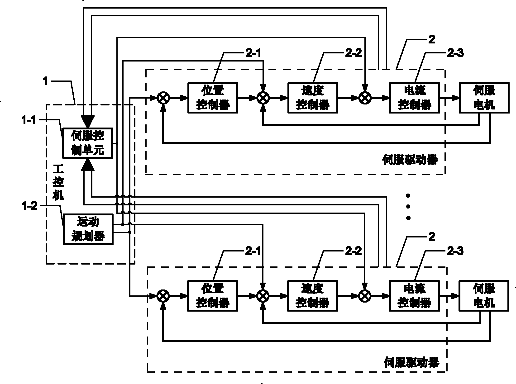
[0017] Specific implementation mode one: the following combination figure 1 Describe the present embodiment, the heavy-duty robot described in the present embodiment has the position controller of acceleration and current feed-forward, and it comprises industrial computer 1 and n servo drives 2;

[0018] The industrial computer 1 includes a servo control unit 1-1 and a motion planner 1-2;

[0019] The servo driver 2 includes a position controller 2-1, a speed controller 2-2 and a current controller 2-3;

[0020] The n position signals output by the motion planner 1-2 are respectively sent to each servo driver 2; the n speed feed-forward signals output by the motion planner 1-2 are respectively sent to each servo driver 2; the servo control unit 1-1 outputs n current feedforward signals are given to each servo driver 2 respectively; the drive signal of each servo driver 2 is fed back to the servo control unit 1-1, and the drive signal includes a position feedback signal, a spe...

specific Embodiment approach 2

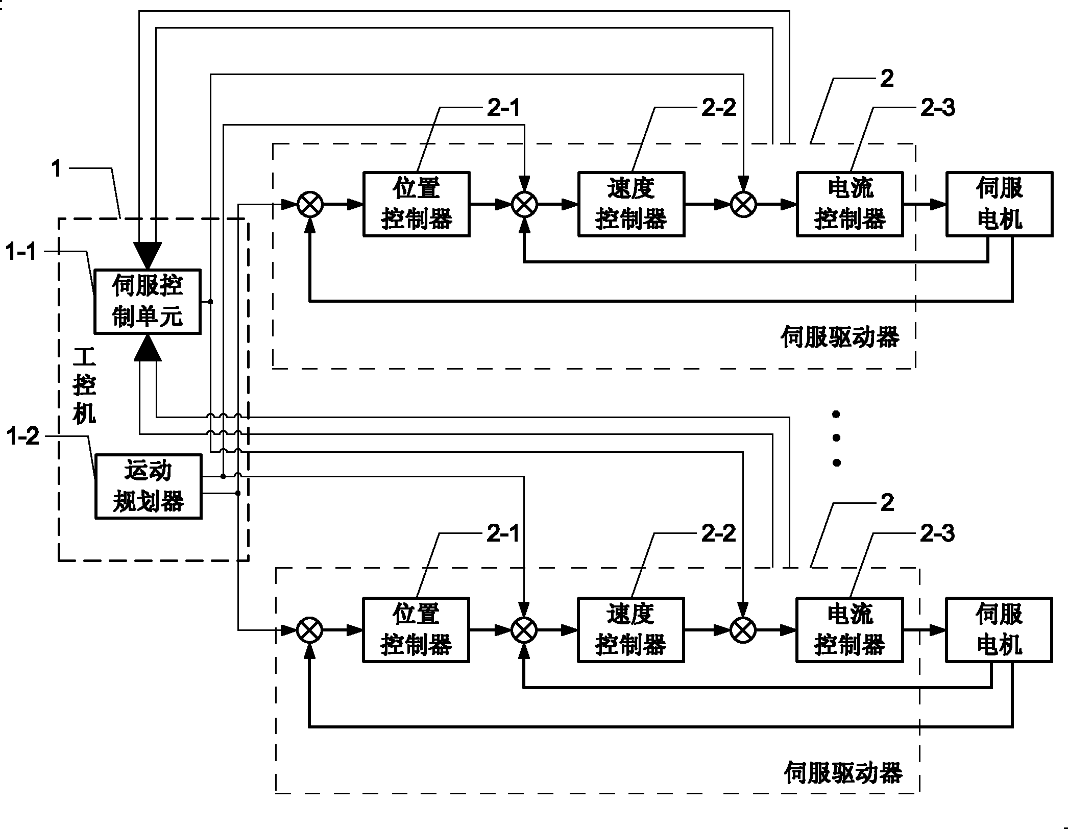
[0024] Specific implementation mode 2: This implementation mode provides a specific example, n=6, that is, the controller has 6 servo drives 2 . The position controller with acceleration and current feed-forward of described heavy load robot, it comprises industrial computer 1 and 6 servo drives 2;

[0025] The industrial computer 1 includes a servo control unit 1-1 and a motion planner 1-2;

[0026] The servo driver 2 includes a position controller 2-1, a speed controller 2-2 and a current controller 2-3;

[0027] The position signal output by the motion planner 1-2 is sent to each servo driver 2 respectively; the speed feedforward signal output by the motion planner 1-2 is sent to each servo driver 2 respectively; the current feedforward signal output by the servo control unit 1-1 To each servo driver 2 respectively; the driving signal of each servo driver 2 is fed back to the servo control unit 1-1, and the driving signal includes a position feedback signal, a speed feedba...


PUM


Abstract

The invention provides a position controller with acceleration and current feedforward for a heavy-load robot, belonging to the robot control field. The invention aims at solving the problem that a traditional linear control mode with single input and single output can not meet the application requirement. The position controller comprises an industrial control machine and n servo drivers, wherein the industrial control machine comprises a servo control unit and a motion planner; each servo driver comprises a position controller, a speed controller and a current controller; the industrial control machine outputs n position speed feedforward and current feedforward signals and sends the signals to each servo driver respectively; each servo control unit receives a feedback position signal and a feedback speed signal; each servo drive has the same control mode; the position signal and the feedback position signal are added together to be used as the input of the position controller; the output of the position controller and the feedback speed signal and the feedforward speed signal are added together to be used as the input of the speed controller; the output of the speed controller and the feedforward current signal are added together to be used as the input of the current controller; and the output of the current controller controls the servo motor to run.

Description

technical field [0001] The invention relates to a position controller with acceleration and current feedforward for a heavy-duty robot, which belongs to the field of robot control. Background technique [0002] The control of high-speed and heavy-duty robots is a complex motion control problem. The traditional single-input-single-output linear control method cannot meet the application requirements, because with the large load and high-speed operation, the dynamic nonlinear term will become very obvious. Conventional PID control with single input and single output will encounter performance bottlenecks. It needs to be nonlinearly decoupled and compensated based on the dynamic model. However, the current domestic mainstream robot control system or motion control system for CNC machine tools generally adopts an industrial computer plus a board, or directly uses an embedded system to complete. It is still unable to meet the application requirements of high-speed heavy-duty in...

Claims


Application Information

Patent Timeline
IPC IPC(8): G05D3/12
Inventor 孔民秀游玮李瑞峰
Owner HARBIN INST OF TECH
Features
  • R&D
  • Intellectual Property
  • Life Sciences
  • Materials
  • Tech Scout
  • Unparalleled Data Quality
  • Higher Quality Content
  • 60% Fewer Hallucinations
Learn More