Controlling and optimizing method of grid-combining three-phase voltage source converter in accumulator storage system

A three-phase voltage, optimization method technology, applied in the direction of AC power input conversion to DC power output, electrical components, AC network load balancing, etc., can solve problems such as difficult system tuning and complex variables in the control system

Active Publication Date: 2011-08-17
JIANGSU HOLLY ELECTRIC
View PDF7 Cites 15 Cited by
  • Summary
  • Abstract
  • Description
  • Claims
  • Application Information

AI Technical Summary

Problems solved by technology

[0005] In order to solve the problem in the prior art that the three-phase voltage source converter of the battery energy storage system uses the method of controlling the DC bus voltage to charge and discharge the battery, which makes the control system extremely complex and has many variables, and the system is difficult to adjust. The present invention provides a A control optimization method for a three-phase voltage source converter that can accurately control the charge and discharge power of the battery energy storage system without controlling the charge and discharge current of the battery energy storage system by controlling the voltage of the DC bus capacitor. The specific scheme is as follows: A control optimization method for a battery energy storage grid-connected three-phase voltage source converter, characterized in that it includes the following steps:

Method used


Image

  • Controlling and optimizing method of grid-combining three-phase voltage source converter in accumulator storage system
  • Controlling and optimizing method of grid-combining three-phase voltage source converter in accumulator storage system
  • Controlling and optimizing method of grid-combining three-phase voltage source converter in accumulator storage system

Examples


Embodiment 1

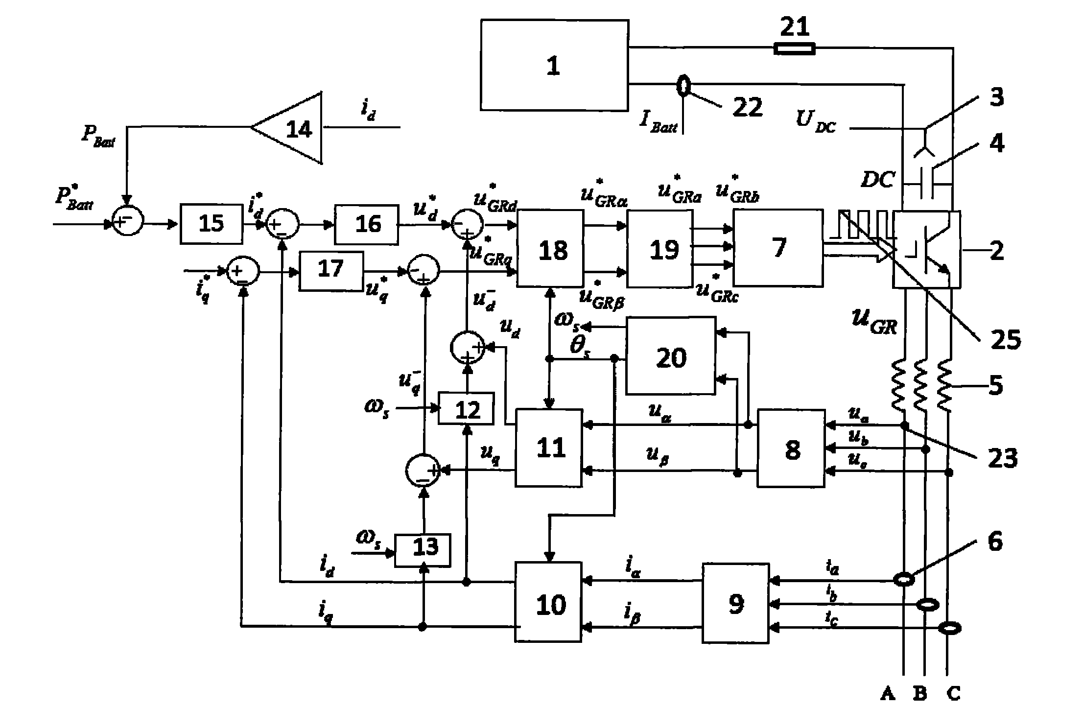
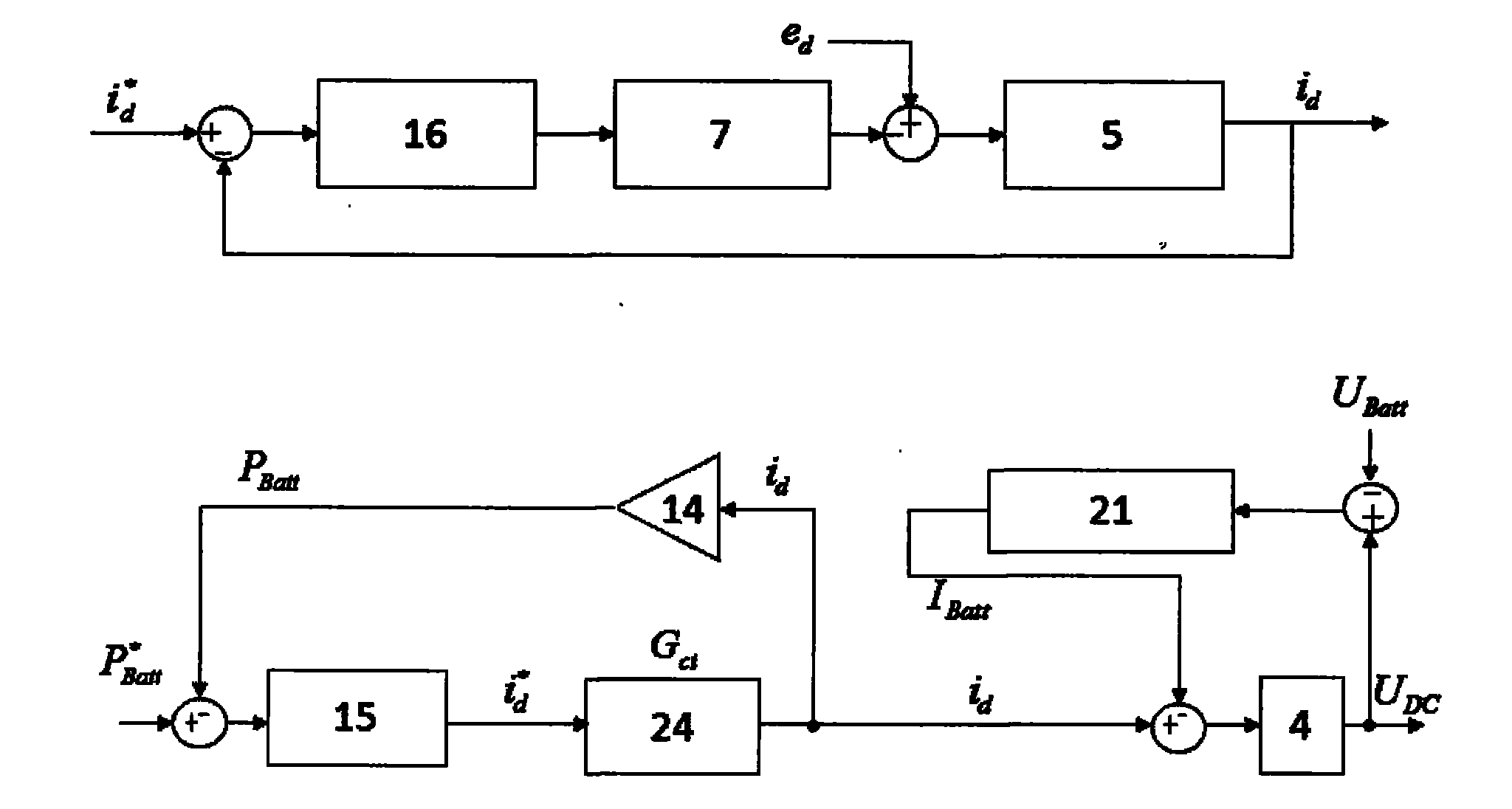
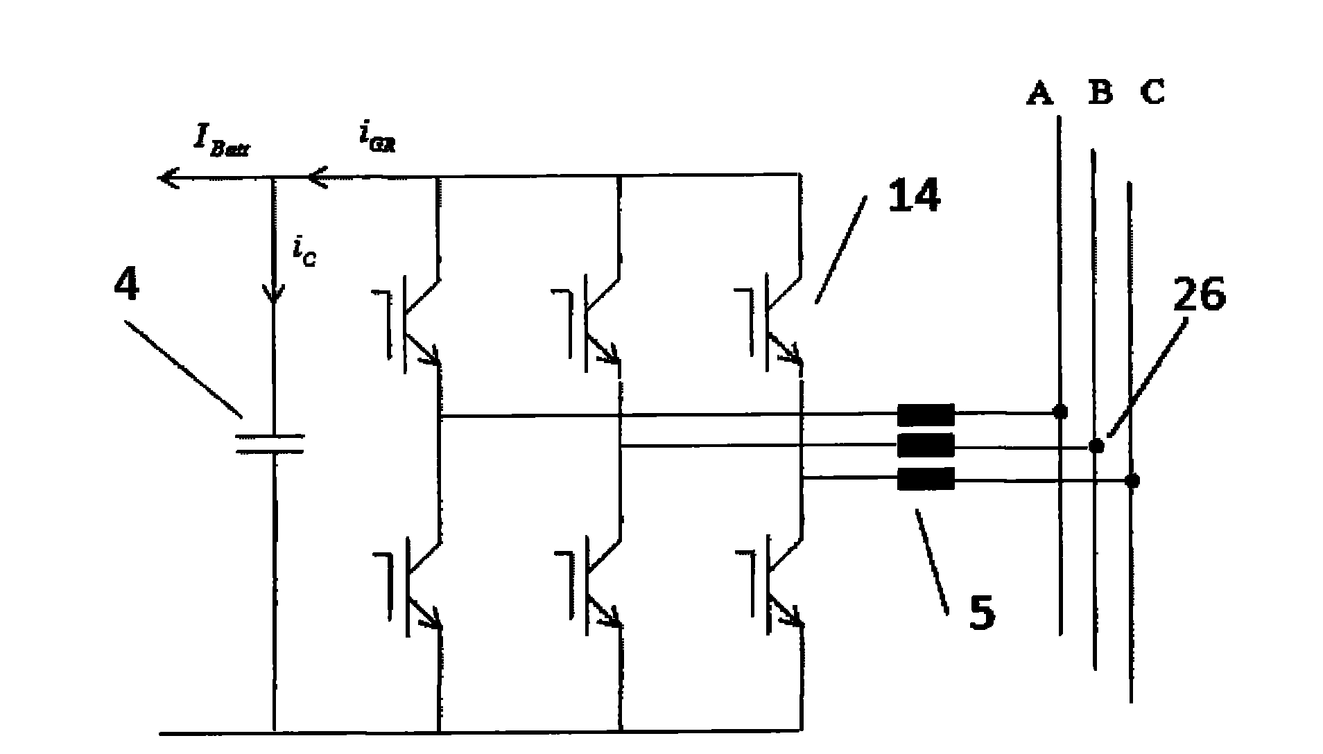
[0026] Such as figure 1 , 2 , 3, this program takes a 100Kw voltage source converter as an example to illustrate the implementation process, including the grid voltage high-pass filter 26, inductive reactance 5, IGBT switch tube 14, DC side bus capacitor 4 and battery 1 And cable inductive reactance 21 composition. The charging reference power jumps from the initial 100Kw to -100Kw (discharging) in 0.03 seconds, the DC bus capacitance is 400uF, the battery SOC state is 50%, the ambient temperature is 25°C, the internal resistance of the battery is 0.3418Ω, the open circuit voltage of the battery is 720V, and the cable resistance is 0.001Ω , cable reactance 10e-6H, switching frequency 15KHz, current PI regulator Kp_i=2.4Ki_i=28.5, power PI regulator Kp_p=0.00136, Ki_p=20.4;

[0027] The control optimization method of the battery energy storage grid-connected three-phase voltage source converter includes the following steps:

[0028] i. Use the single-phase Hall sensor 3 to c...


PUM


Abstract

The invention discloses a controlling and optimizing method of s grid-combining three-phase voltage source converter in an accumulator storage system, belonging to the field of electricity storage. The method comprises the following steps of: collecting signals of voltage and the three-phase electric grid current, performing Clark conversion and Park conversion to convert into two-phase fixed axis variable using as a feedback quantity, and counting charging power, comparing the feedback power with reference power, performing PI regulation and then outputting, wherein the output value is a reference value of active current, synchronously setting a reference value of passive current, comparing the reference values of the active current and the passive current with a rotating shaft two-phase current which is converted from the three-phase electric grid current, and performing the PI regulation to obtain a reference voltage, performing the Clark reverse conversion and the Park reverse conversion to obtain the fixed coordinate system voltage of the output end of the three-phase converter. The controlling and optimizing method of grid-combining three-phase voltage source converter in accumulator storage system can directly control the grid-combining active power of the converter, thus the loop is simple to control, the three-stage system is changed into a two-stage system, the system is easy to optimize and the system is stable and reliable.

Description

technical field [0001] The invention relates to electric power grid-connected energy storage technology in the electric power industry, in particular to a control optimization method for a battery energy storage grid-connected three-phase voltage source converter system designed for grid stability. Background technique [0002] With the continuous development of global new energy technologies, especially the increasing development and utilization of wind energy and solar energy, the energy flow of the power grid has fluctuated, which poses a great challenge to the stability of the power grid. In order to make the power grid more stable and To be strong, there needs to be a device that can cut peaks and fill valleys for grid energy. Now foreign countries have started research on grid energy storage systems. With the huge development of wind energy resources in recent years, China has also started energy storage systems. The battery energy storage system is one of the most pro...

Claims


Application Information

Patent Timeline
Patent Type & Authority Applications(China)
IPC IPC(8): H02M7/797H02J3/28
Inventor 施俊
Owner JIANGSU HOLLY ELECTRIC
Why Eureka
Try Eureka