Elastic thermal conduction structure for multiple heat sources of fanless electronic device

An electronic device, elastic heat conduction technology, applied in the direction of cooling/ventilation/heating transformation, etc., can solve problems such as uneven surface, poor heat dissipation, poor

Active Publication Date: 2011-08-17
ADLINK TECH INC
View PDF3 Cites 13 Cited by
  • Summary
  • Abstract
  • Description
  • Claims
  • Application Information

AI Technical Summary

Problems solved by technology

[0004] However, for this kind of heat conduction structure with multiple heat sources, in the face of the need to use thinner (low thermal resistance coefficient, less compression) thermal pads or thinner thermal paste, it is often due to computer housing tolerances (such as process, material etc.) caused by uneven surface or tiny defects, so that the thermal pad or heat dissipation paste can not touch the surface of the chip, or the poor thermal conductivity caused by the inability to make a good contact, even during the assembly pr

Method used


Image

  • Elastic thermal conduction structure for multiple heat sources of fanless electronic device
  • Elastic thermal conduction structure for multiple heat sources of fanless electronic device
  • Elastic thermal conduction structure for multiple heat sources of fanless electronic device

Examples


Embodiment Construction

[0036] In order to achieve the above-mentioned purpose and effect, the technical means and structure adopted by the present invention, the features and functions of the preferred embodiments of the present invention will be described in detail as follows, so as to facilitate a complete understanding.

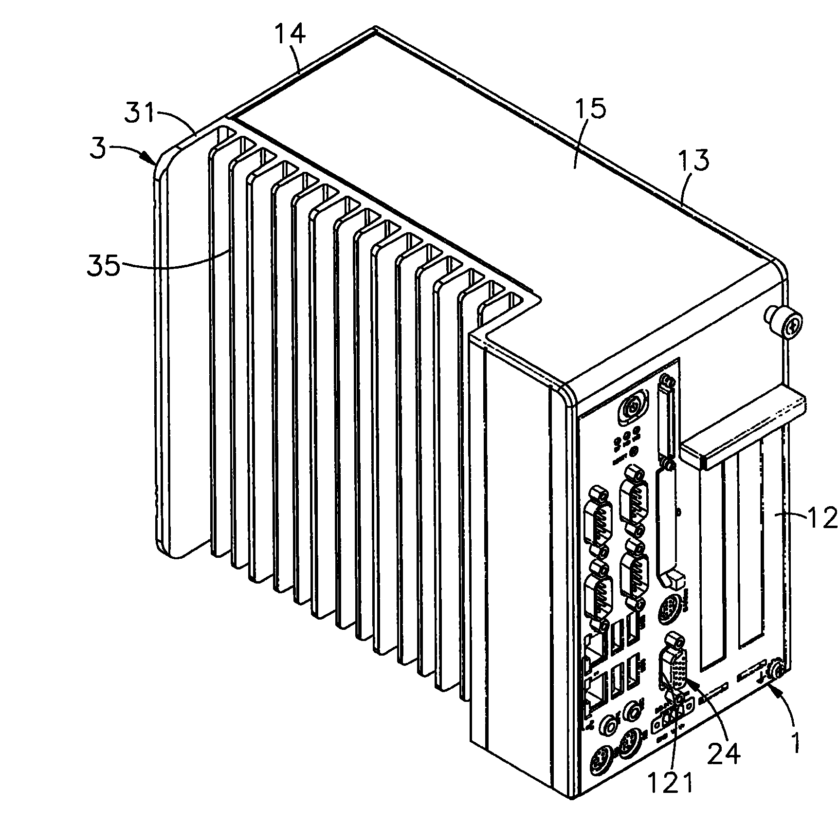
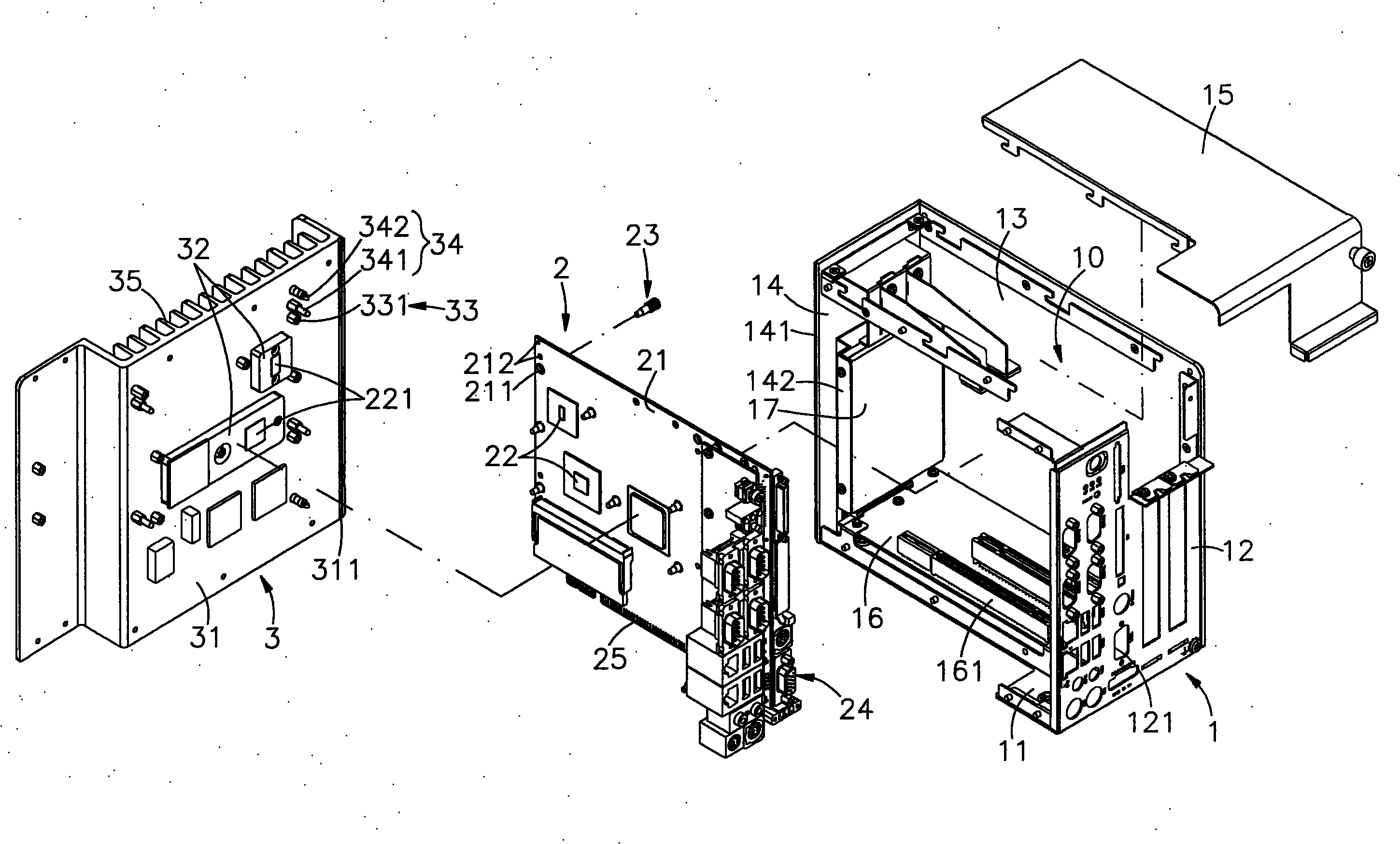
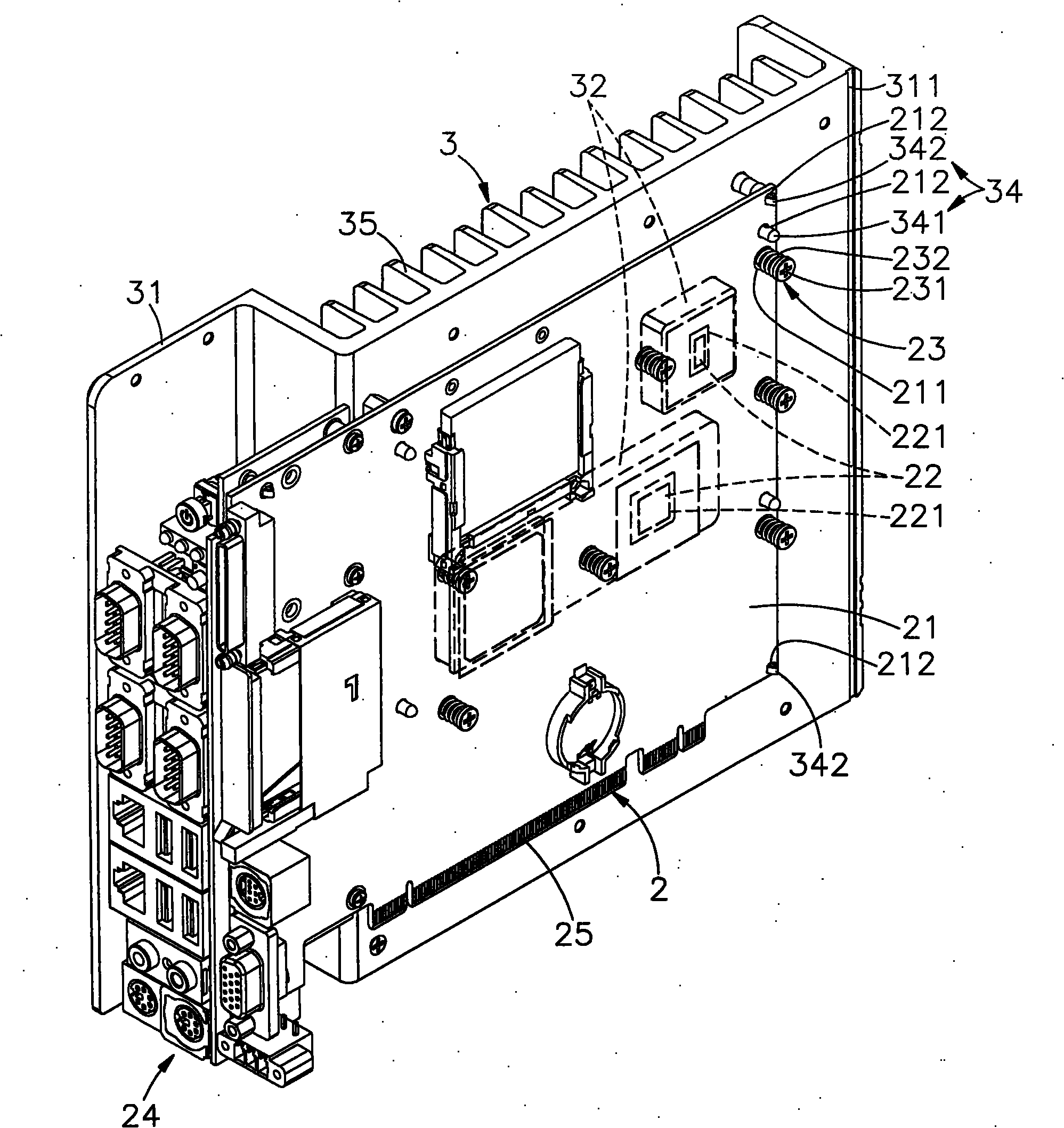
[0037] see figure 1 , 2 , 3, and 4 are respectively the three-dimensional appearance diagram of the present invention, the three-dimensional exploded view, the three-dimensional appearance diagram of the preferred embodiment, and image 3 It can be clearly seen from the partially enlarged diagram that the present invention includes an organic casing 1, a circuit module 2 and an outer casing 3, so the main components and their characteristics of this case are described in detail below, wherein:

[0038] The casing 1 has a base 11, and a docking shell 12 with a plurality of through holes 121 is vertically provided on one side of the base 11, and an outer shell 13 is extended on o...


PUM

PropertyMeasurementUnit
Thicknessaaaaaaaaaa

Abstract

The invention provides an elastic thermal conduction structure for multiple heat sources of a fanless electronic device. The invention adopts the following technical scheme: the structure comprises a case and an outer shell, wherein housing space capable of housing a circuit substrate is formed inside the case; the circuit substrate is provided with a plurality of heating sources in different height; two or more through holes for elastic positioning parts to penetrate through and a plurality of joint holes arranged at the corners outside the through holes are respectively arranged around eachheating source so that the outer shell is combined at the side of the case; thermal conduction media are arranged in preset gaps respectively formed by a plurality of protruding parts on the inner side wall surface of a radiating base of the outer shell and the heating sources; a plurality of positioning portions at the corners outside the protruding parts respectively penetrate through the jointholes on the circuit substrate; then the elastic positioning parts are locked in corresponding fixing portions around the protruding parts to form a whole; and the thermal conduction media can be thermal pads or radiating grease to ensure good elastic pushing and sticking and close states between the heating sources and the protruding parts on the radiating base so as to effectively reduce the thermal resistance, so the integral thermal conduction effect can be improved.

Description

technical field [0001] The invention provides an elastic heat conduction structure with multiple heat sources for a fanless electronic device, especially the outer casing is combined with the side of the casing, so that the multiple protrusions on the wall surface of the cooling seat and the heat sources of different heights on the circuit board are provided. The predetermined gap is provided with a heat conduction medium, and forms a good elastic contact and close contact state, supplemented by effectively reducing thermal resistance and improving the effect of overall heat conduction. Background technique [0002] With the advent of today's diversified information age, all kinds of electronic products are flooding around the living environment. With the continuous innovation and progress of science and technology, electronic products are also moving toward multi-function, purpose and additional hardware equipment. Many All electronic products use computers to control their...

Claims


Application Information

Patent Timeline
IPC IPC(8): H05K7/20
Inventor 邱建霖
Owner ADLINK TECH INC
Why Eureka
Try Eureka