Inductively receiving electric energy for vehicle

A vehicle and electric energy technology, applied in the direction of vehicle energy storage, electric energy management, vehicle components, etc., can solve problems such as interference, and achieve the effect of solving wear and tear problems

Active Publication Date: 2011-08-17
BOMBARDIER TRANSPORTATION GMBH
View PDF6 Cites 26 Cited by
  • Summary
  • Abstract
  • Description
  • Claims
  • Application Information

AI Technical Summary

Problems solved by technology

On the one hand, electromagnetic fields may interfere with devices of other technologies

Method used


Image

  • Inductively receiving electric energy for vehicle
  • Inductively receiving electric energy for vehicle
  • Inductively receiving electric energy for vehicle

Examples


Embodiment Construction

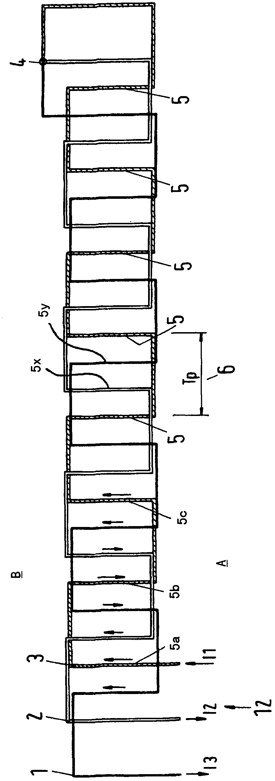
[0110] figure 1 Shows a conductor arrangement that may be located below ground along a track, for example, along a railroad track (see, for example, Figure 11 configuration shown). figure 1 The middle rail can extend from left to right.

[0111] figure 1 It should be understood as a schematic diagram. The three lines 1 , 2 , 3 of the conductor arrangement comprise sections extending transversely to the direction of travel (from left to right or from right to left). Only some of the laterally extending parts of the lines 1, 2, 3 are indicated with reference numerals, that is, the three parts 5a, 5b and 5c of the line 3, other parts of the line 3 are indicated with "5", the line part 5x of line 2 and part 5y of line 1. In the most preferred case, figure 1 The configuration shown in 12 is located below the track floor or in railroad ties, thus figure 1 A top view of configuration 12 is shown. The track can extend from left to right, at figure 1 The top and bottom of the...


PUM


Abstract

The invention relates to an arrangement for providing a vehicle, in particular a track bound vehicle, with electric energy, wherein the arrangement comprises a receiving device (200) adapted to receive an alternating electromagnetic field and to produce an alternating electric current by electromagnetic induction. The receiving device (200) comprises a plurality of windings and / or coils (9, 10, 11) of electrically conducting material, wherein each winding or coil (9, 10, 11) is adapted to produce a separate phase of the alternating electric current.

Description

technical field [0001] The invention relates to an arrangement, a system and a method for providing energy to a vehicle, in particular a rail vehicle, by using a receiving device adapted to receive an alternating electromagnetic field and use electromagnetic induction to generate an alternating current. In particular, the invention has application in providing propulsion energy to light rail vehicles (eg trams). Background technique [0002] In certain rail vehicles, such as conventional rail vehicles, monorail vehicles, tram buses and vehicles guided on rails by other means (e.g. by other mechanical, magnetic, electronic and / or optical means), Energy is required for propulsion on this track and to operate auxiliary systems that do not generate vehicle traction. Such auxiliary systems are, for example, lighting systems, heating and / or air conditioning systems, ventilation and passenger information systems. More specifically, however, the invention concerns the delivery of ...

Claims


Application Information

Patent Timeline
Patent Type & Authority Applications(China)
IPC IPC(8): B60L5/00B60M7/00B60L9/08B60L50/13
CPCB60L11/182Y02T90/122Y02T10/7088Y02T10/7005Y02T10/725Y02T90/14Y02T90/127B60L2210/20B60L2200/26B60L5/005B60M7/00B60L53/12Y02T10/72B60L9/08Y02T10/7072Y02T10/70Y02T90/12
Inventor K·福伦怀德J·迈因斯C·施特鲁韦
Owner BOMBARDIER TRANSPORTATION GMBH
Why Eureka
Try Eureka