
Injection device capable of adapting to low-temperature environment in foam drainage gas recovery

A foam drainage and injection device technology, which is applied in the direction of mining fluid, earthwork drilling, wellbore/well components, etc., can solve the problems of no industrial power supply, low ambient temperature, and the inability to effectively use foam drainage gas recovery technology, etc., to achieve Ease of transportation and compact structure

Inactive Publication Date: 2011-08-24
SOUTHWEST PETROLEUM UNIV
View PDF6 Cites 15 Cited by
  • Summary
  • Abstract
  • Description
  • Claims
  • Application Information

AI Technical Summary

Problems solved by technology

[0004] The purpose of the present invention is: to solve the problem of liquid-loaded gas wells without industrial power supply and low ambient temperature, which cannot effectively use foam drainage and gas recovery technology, timely eliminate liquid-loaded gas wells and defoaming of produced fluids, a special proposal is made A foam drainage gas recovery injection device adapted to low temperature environment

Method used


Image

  • Injection device capable of adapting to low-temperature environment in foam drainage gas recovery
  • Injection device capable of adapting to low-temperature environment in foam drainage gas recovery
  • Injection device capable of adapting to low-temperature environment in foam drainage gas recovery

Examples


Embodiment Construction

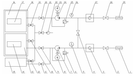
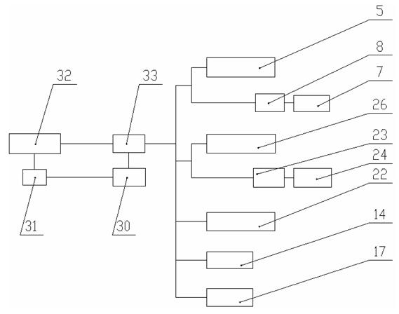
[0012] according to figure 1 , figure 2 As shown, the structural feature of the foam drainage and gas production injection device adapted to the low temperature environment is that the liquid filling pump 22 is connected to the ball valve 21 with a low-pressure pipeline, and then the ball valve 19, the ball valve 10, and the ball valve 12 are connected in parallel. The outlet end of 10 is connected to the chemical pool 13, the outlet end of the ball valve 12 is connected to the antifreeze tank 15, the electric heater 14 is set in the chemical pool 13, the electric heater 17 is set in the chemical pool 16, and exhaust jackets are installed around the chemical pool 13 and the chemical pool 16 18. The quick connector 1 is connected to the cut-off valve 2 with a pipeline, and then connected to the check valve 3. The other end of the check valve 3 is connected to the cut-off valve 4 with a three-way branch pipeline, and an electric contact pressure gauge 5 and a pressure gauge 5 a...


PUM


Abstract

The invention discloses an injection device capable of adapting to a low-temperature environment in foam drainage gas recovery, which is applied to a water-bearing natural gas field and can overcome the difficulties of removing liquid accumulations of the well shaft in the gas well with accumulated liquids and removing foams in the produced fluids under the conditions of no commercial power supply and low ambient temperature. The technical scheme adopted in the invention is as follows: a liquid feeding pump is connected with ball valves through a pipe and then connected in parallel with a chemical tank I, a chemical tank II and an anti-freezing agent tank through the ball valves; heaters are arranged inside the chemical tanks; tail gas jackets are arranged at the periphery of the chemical tanks; a first quick-acting coupling is connected with a first cut-off valve and a first one-way valve through a pipe and then connected with a first electric contact pressure gauge, a first plunger pump and a first motor; the outlet end of the first plunger pump is connected with the ball valves respectively and then connected with the chemical tanks and the anti-freezing agent tank; a second quick-acting coupling is connected with a second cut-off valve and a second one-way valve through a pipe and then connected with a second electric contact pressure gauge, a second plunger pump and a second motor; the outlet end of the second plunger pump is connected with the chemical tanks; and an oil-fired generator and an electric control system form a circuit system. The injection device has compact structure, is convenient in transportation, is suitable for the actual environments in natural gas field production, and improves the drainage gas recovery effect.

Description

technical field [0001] The invention relates to a foam drainage gas recovery injection device suitable for low-temperature environment, which is used for foam drainage gas recovery in water-containing gas fields in the natural gas industry. technical background [0002] With the deepening of the development of water-bearing gas fields, the energy of the formation gradually decreases, and the pressure of the gas reservoir decreases continuously, which often leads to the formation water or condensate in the wellbore of the gas well not being carried out of the wellbore by the natural gas flow immediately, resulting in the phenomenon of wellbore fluid accumulation. Seriously affect the normal production of gas wells, and even flood the gas wells. Timely removal of fluid accumulation in the wellbore is particularly important for the normal production of gas wells. Foam drainage and gas recovery technology is one of the technologies widely used in large field drainage and gas rec...

Claims


Application Information

Patent Timeline
IPC IPC(8): E21B43/16E21B43/22
Inventor 梁政邓雄王飞蒋发光张梁叶哲伟
Owner SOUTHWEST PETROLEUM UNIV
Learn More