
Multi-arc chute processing machine box

A technology for processing casings and arcs, applied in mechanical equipment, machines/engines, liquid fuel engines, etc., can solve problems such as unreasonable geometric structure design of processing tanks, reduced adiabatic efficiency, and reduced peak compressor efficiency.

Inactive Publication Date: 2011-08-24
BEIHANG UNIV
View PDF3 Cites 11 Cited by
  • Summary
  • Abstract
  • Description
  • Claims
  • Application Information

AI Technical Summary

Problems solved by technology

[0006] Summing up the traditional casing technology, there is such a disadvantage: while improving the stability margin of the compressor, it is always at the cost of reducing the insulation efficiency
In an aero engine, the reduction in the adiabatic efficiency of the compressor means that the fuel consumption will be more
[0007] One of the most important reasons why the traditional treatment casing will reduce the peak efficiency of the compressor is the unreasonable design of the geometric structure of the treatment tank
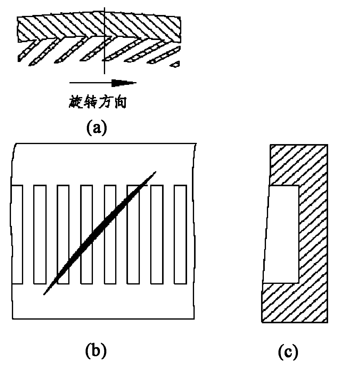
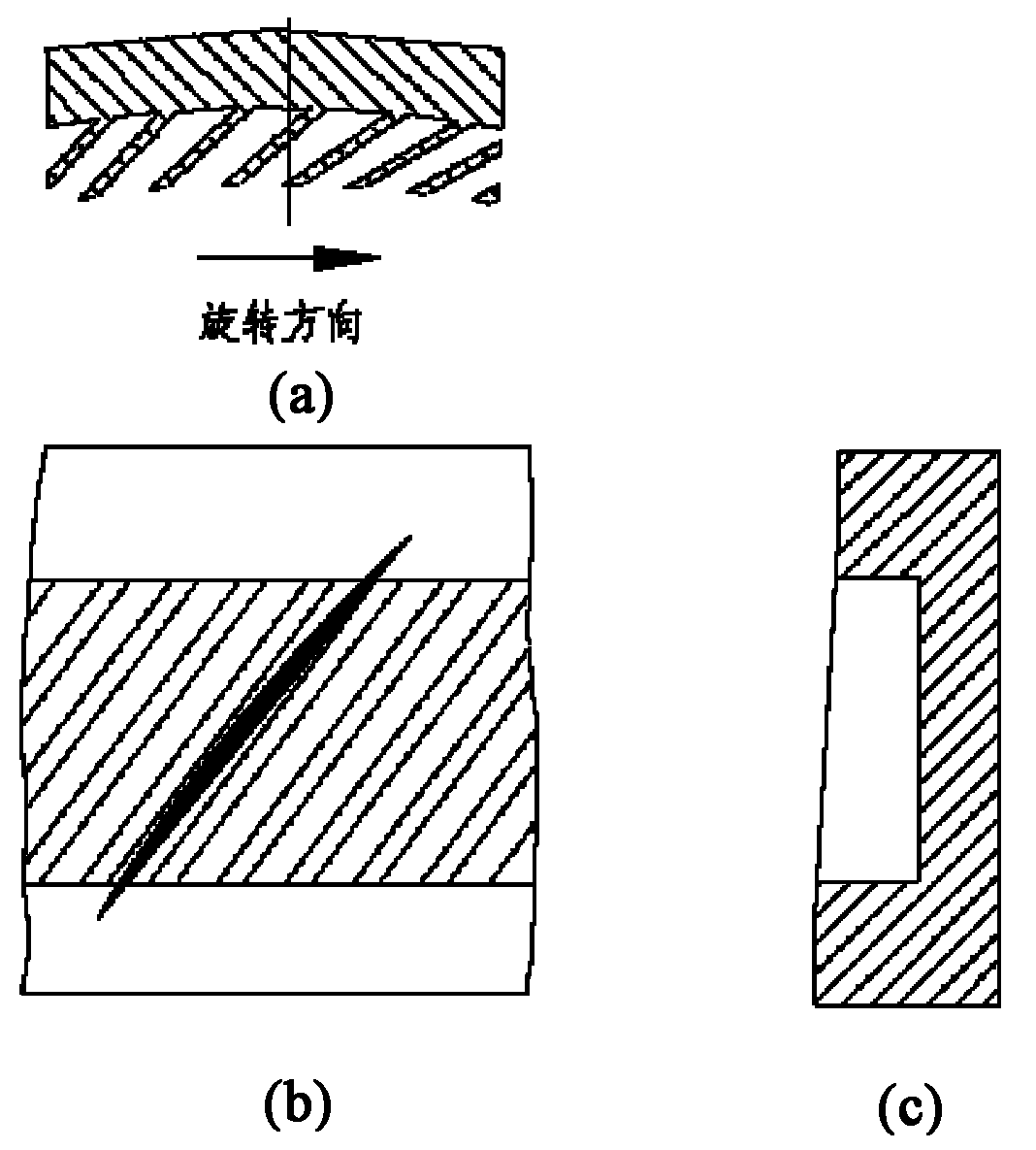
At least one of the processing grooves of the traditional processing casing has a rectangular or trapezoidal design in the three directions of R (radial direction), Z (axial direction) and θ (circumferential direction), and the front and rear parts of the processing groove are in line with the The radial angle is mostly designed to be 0°, which will inevitably increase the mixing loss between the airflow ejected from the treatment tank and the main flow area

Method used


Image

  • Multi-arc chute processing machine box
  • Multi-arc chute processing machine box
  • Multi-arc chute processing machine box

Examples


Embodiment Construction

[0028] Taking a single rotor of a transonic compressor as an example to illustrate the specific implementation of the present invention, Table 1 shows the basic aerodynamic and structural parameters of the single rotor of the transonic compressor.

[0029] Table 1 Design parameters of transonic axial flow compressor rotor

[0030]

[0031]

[0032] Carry out following design according to the design method in the summary of the invention:

[0033] (1) Determine the number of processing tanks N=17×6=102

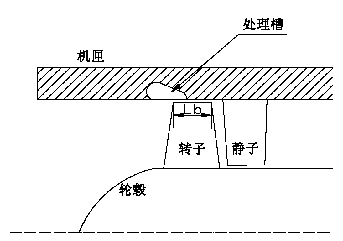
[0034] (2) The axial projection length L of the treatment tank H =1.085×35mm=38mm, L b =35mm

[0035] (3) The radial inclination angle Alpha of the treatment tank is 45°

[0036] (4) The radii of the two arcs are R1=14mm; the angle between the line connecting the two ends of the semi-arc at the front (that is, the diameter) and the casing line is 50°

[0037] (5) The treatment tank adopts an arc shape in Z (axial direction), the overlap of the treatment tank is 35%, ...


PUM


Abstract

The invention relates to a multi-arc chute processing machine box applying to a rotor blade tip end region of an axial flow compressor. For the design of the multi-arc chute processing machine box, the greater flow loss of the processing chute caused by the rectangular and trapezoid design of the traditional processing machine box is taken into account. Through the reasonable design of a geometric construction type of the processing chute, namely the combination design that a double-arc shape is adopted at the direction of the R direction and a circular arc shape is adopted for theta (circumference), the greater low loss caused by the rectangular and trapezoid design is avoided, thus the peak value efficiency is improved slightly, meanwhile the stall margin of the compressor is improved greatly for the multi-arc chute processing machine box.

Description

technical field [0001] The invention relates to a device for improving the stability margin of a compressor, in particular to a multi-arc chute processing casing which can obviously improve the stability margin of a compressor while slightly improving its peak efficiency. Background technique [0002] Compressors are widely used in aero-engines and industrial production. With the continuous improvement of the load factor of the compressor stage, the unstable flow of the compressor becomes more and more prominent, such as rotating stall, surge, etc., which greatly limits the further improvement of the performance of the compressor. When rotating stall occurs, there are one or more low-energy stall clusters rotating along the circumference of the compressor, the performance of the compressor will suddenly drop, the flow rate, pressure ratio and efficiency will all drop to the lowest point, and the compressor blades will be periodically damaged. Exciting force, even cause the ...

Claims


Application Information

Patent Timeline
IPC IPC(8): F04D29/40F04D29/66
CPCF04D29/685
Inventor 李志平袁巍李茂义陆亚钧
Owner BEIHANG UNIV
Learn More