Pipe clamp with vibration absorption structure for automobile

A vibration-damping structure and pipe clamp technology, applied in the direction of pipe supports, pipes/pipe joints/pipes, mechanical equipment, etc., can solve the problem that the insertion and extraction force of projection welding bolts cannot be adjusted, the vibration and noise of the whole vehicle are high, and the axial direction of the pipe can not be adjusted. To avoid problems such as moving, to achieve the effect of convenient and reliable assembly, adjustable vibration damping effect, and not easy to fall off

Inactive Publication Date: 2011-08-24
CHONGQING CHANGAN AUTOMOBILE CO LTD
View PDF5 Cites 8 Cited by
  • Summary
  • Abstract
  • Description
  • Claims
  • Application Information

AI Technical Summary

Problems solved by technology

At present, the fixing groove of the pipe clip used to fix the oil pipe is semi-open, and the pipe is directly stuck in the fixing groove of the pipe clip. Axial movement easily occurs in the fixed groove
When the pipe diameter of the corresponding pipe changes, different pipe clips need to be developed, and the development cost is high
The installation method is fixed by screwing the projection welding bolts through the installation holes, and there are the following disadvantages: first, the projection welding bolts are directly inserted into the installation holes during installation, and the insertion force is too large, which consumes the physical strength of the workers; second, due to installation or disassembly During the process, the matching surface of the projection welding bolt in the mounting hole is damaged, and it is not suitable for repeated use; the third is that the insertion and extraction force of the projection welding bolt cannot be adjusted
In this installation method, there is a hard connection between the pipe clamp and the body, and a hard connection between the pipe and the pipe clamp, so that the vibration generated by the flow of liquid in the pipe during the operation of the vehicle and the vibration caused by the external interference of the pipe directly pass through the pipe. The card is transmitted to the body, which directly causes the vibration and noise of the whole vehicle to be high

Method used


Image

  • Pipe clamp with vibration absorption structure for automobile
  • Pipe clamp with vibration absorption structure for automobile
  • Pipe clamp with vibration absorption structure for automobile

Examples


Embodiment Construction

[0021] The following set of drawings describe the structure of the pipe clamp in detail:

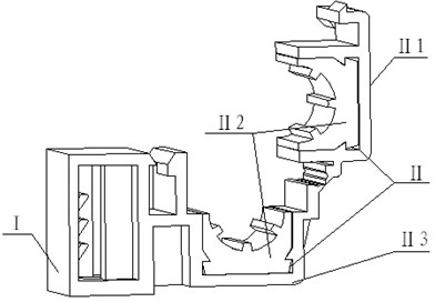
[0022] see figure 1 , The present invention consists of the installation part I and the clamping part II. The installation part I is a frame structure with bolt installation holes, and there are guide teeth I1 and guide columns I2 in the holes. The clamping part Ⅱ is composed of the pipe clamp cover Ⅱ1, the vibration damping pad Ⅱ2 and the pipe clamp seat Ⅱ3. The installation part Ⅰ, the pipe clamp cover Ⅱ1, and the pipe clamp seat Ⅱ3 are connected as a whole through injection molding. The vibration damping pad Ⅱ2 is installed on the pipe clamp cover Ⅱ1 and the pipe clamp seat Ⅱ3 by inlaying, and the pipe clamp cover Ⅱ1 and the pipe clamp seat Ⅱ3 are buckled. to form a clamping hole.

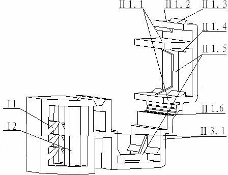
[0023] The matching structure of the installation part Ⅰ and the fixing bolt 1 is detailed in Figure 4 and Figure 5 . The guide teeth Ⅰ1 are symmetrically distributed on both side walls of the bolt...


PUM


Abstract

The invention discloses a pipe clamp with a vibration absorption structure for an automobile, which comprises an installing part and a holding part which are combined into a whole through injection molding, wherein the installing part is provided with a bolt installing hole; the holding part comprises a pipe clamp cover and a pipe clamp seat; one side of the pipe clamp cover and one side of the pipe clamp seat are flexibly hinged, and the other sides are mutually locked and connected; a clamping hole for clamping a pipe is surrounded between the pipe clamp cover and the pipe clamp seat; shock absorption pads are respectively installed on the inner walls of the clamping hole of the pipe clamp cover and the pipe clamp seat; and the shock absorption pads are in contact with the clamped pipe. The pipe clamp disclosed by the invention can reduce the vibration which is transferred to the automobile body from the pipe, has the advantages of adjustable vibration absorption effect of the pipe clamp, simpleness and convenience in assembling, difficulty in drop and adjustable pull-insertion force, can be repeatedly used and can meet the requirement that the assembling of pipes with different pipe diameters does not need to redevelop the integral pipe clamp.

Description

technical field [0001] The invention relates to a pipe clip structure used on automobiles. Background technique [0002] Due to the large span of the automobile fuel pipe, in order to standardize the layout and avoid interference, it is usually necessary to use multiple pipe clamps to fix the fuel pipe to different positions on the vehicle body. At present, the fixing groove of the pipe clip used to fix the oil pipe is semi-open, and the pipe is directly stuck in the fixing groove of the pipe clip. Axial movement easily occurs in the fixing groove. When the pipe diameter of the corresponding pipe changes, different pipe clips need to be developed, and the development cost is high. The installation method is fixed by screwing the projection welding bolts through the installation holes, and there are the following disadvantages: first, the projection welding bolts are directly inserted into the installation holes during installation, and the insertion force is too large, whi...

Claims


Application Information

Patent Timeline
Patent Type & Authority Applications(China)
IPC IPC(8): F16L3/12F16L3/20
Inventor 刘华余虹波邓峰石明祥
Owner CHONGQING CHANGAN AUTOMOBILE CO LTD
Why Eureka
Try Eureka